


P. 6 Installation Guide AS-1820 FM
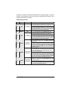
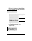
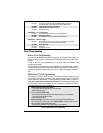
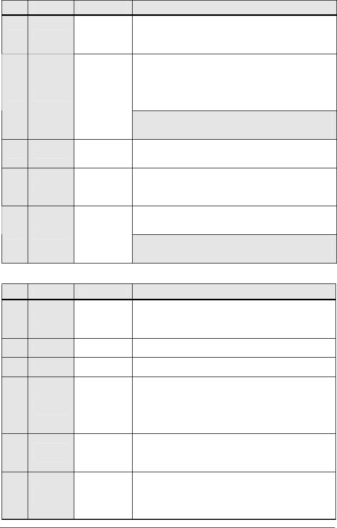
5-Pin Secondary Harness
Wire Colour Function Description
1 BLACK
(–)
Chassis ground
input
This wire must be connected to bare, unpainted metal (the Chassis
or the true Body ground). It is preferable to use a factory ground
bolt rather than a self-tapping screw. Screws tend to get loose or
rusted over time and can cause erratic problems.
This wire will allow the Remote Car Starter to sense whether the
Engine is running. The wire requires at least 1.8 V (AC) and 1.6 Hz
or faster when the Engine runs at idle speed. Among common
references for the Tach wire are: the negative side of the Ignition
Coil, the Camshaft sensor, the Crankshaft sensor or the Engine
Control Module (ECM).
2 PURPLE
(A.C.)
Tachometer
input
Note: if the Tach signal is too low, the Remote Car Starter will
“over-crank”. Conversely, if the Tach signal is too high, the Remote
Car Starter will “under-crank”.
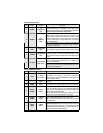
3 GREY
(–) Hood Switch
input
Connect this wire to the installed Hood Pin switch supplied. This
input will disable or shut down the Remote Starter when the Hood is
up.
4 ORANGE
(+) Brake Switch
input
This wire must be connected to the Brake Light wire of the vehicle.
This wire must have +12 V only when the Brake Pedal is down.
This input will shut down the Remote Starter if the Brake Pedal is
pressed.
This wire provides a +12 V output and must be connected on the
vehicle to the Parking Lights wire that tests +12 V when the Light
switch is in the
ON position.
5 YELLOW
(+) 12 V Parking
Light output
Note: ensure that the voltage does not decrease or increase when
the dimmer control switch is turned. If the voltage goes up or down,
find another Parking Light wire.
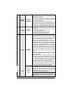
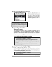
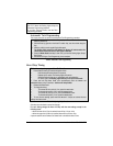
12-Pin Accessories Harness
Wire Colour Function Description
1 BLUE
(–) Trunk /
AUX 3 output
500 mA negative output. This output can be used to control the
Trunk release (1-sec. pulse), or it can be set to operate as a
constant output as long as the TRUNK button is held pressed (for
Sunroof or Window closure)
2 BROWN
(–) Lock
output
Programmable 500 mA negative output: 1/10-sec., 7/10-sec. or 4-
sec. pulse
3 GREEN
(–) Unlock
output
Programmable 500 mA negative output: 1/10-sec., 7/10-sec., 4-
sec. or double 1/4-sec. pulse (
ON 250 ms, OFF 500 ms, ON 250 ms).
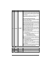
4
WHITE /
BROWN
(–) Rearm
output
500 mA ground signal when the Doors are locked by remote
control. This wire will go to ground 1/2 sec. before the
LOCK pulse,
and go out 1/8 sec after
LOCK. The wire must be connected to the
OEM Arm wire (usually the Door Pin).
Note: The Remote Car Starter will also give a Rearm pulse on this
wire when it shuts down the vehicle after a remote start.
5
WHITE /
GREEN
(–) Disarm
output
500 mA ground pulse when the Doors are unlocked by remote
control. Connect to the OEM Disarm wire of the vehicle.
Note: The system will also give a Disarm pulse on this wire before
every remote start.
6
BLUE /
WHITE
(–) AUX 1
output
Depending on the configuration of Mode 3, Function 4 (see
Programming Options later in this Guide), this output will provide
either a 500 mA ground output on the 2
nd
consecutive press of the
UNLOCK button for Priority Door Access, or a Horn Confirmation on
the first or second press of the
LOCK button.