


AS-1725 SH Installation Guide P. 5
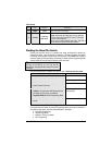
This wire will power the Heater Blower Motor. Usually connected
to the Accessories wire of the vehicle. The source wire must have
power with the Ignition Key in the
IGNITION ON (RUN) position only
(no power in the
CRANK position).
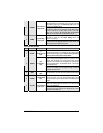
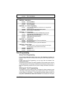
E ORANGE
(+) Accessories
output (30 A)
Warning: at the Ignition Switch of certain vehicles, there may be
more than one Ignition wire for powering the Heater Blower Motor.
Use the 5
th
relay (Pin F) and extra relays to power up any extra
Ignition wires if necessary. Do not jump wires at the Ignition
Switch: this would compromise the OEM electrical system.
This high-current output can be used to power a second Ignition,
Accessories or Crank wire. See Jumper Setting, later in this
Guide, for correct output.
F GREEN
(+) Fifth Relay
output (30 A)
Please note: additional Ignition, Accessories, or Starter wires must
use external relays. Do not jump wires at the Ignition Switch: this
would compromise the OEM electrical system.
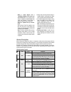
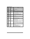
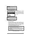
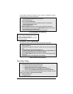
5-Pin Secondary Harness
Wire Colour Function Description
1 BLACK
(–)
Chassis ground
input
This wire must be connected to bare, unpainted metal (the Chassis
or the true Body ground). It is preferable to use a factory ground
bolt rather than a self-tapping screw. Screws tend to get loose or
rusted over time and can cause erratic problems.
This wire will allow the Remote Car Starter to sense whether the
Engine is running. The wire requires at least 1.8 V (AC) and 1.6 Hz
or faster when the Engine runs at idle speed. Among common
references for the Tach wire are: the negative side of the Ignition
Coil, the Camshaft sensor, the Crankshaft sensor or the Engine
Control Module (ECM).
2 PURPLE
(A.C.)
Tachometer
input
Note: if the Tach signal is too low, the Remote Car Starter will
“over-crank”. Conversely, if the Tach signal is too high, the Remote
Car Starter will “under-crank”.
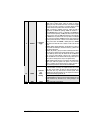
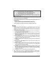
3 GREY
(–) Hood Switch
input
Connect this wire to the installed Hood Pin switch supplied. This
input will disable or shut down the Remote Starter when the Hood is
up.
4 ORANGE
(+) Brake Switch
input
This wire must be connected to the Brake Light wire of the vehicle.
This wire must have +12 V only when the Brake Pedal is down.
This input will shut down the Remote Starter if the Brake Pedal is
pressed.
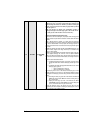
This wire provides a +12 V output and must be connected on the
vehicle to the Parking Lights wire that tests +12 V when the Light
switch is in the
ON position.
5 YELLOW
(+) 12 V Parking
Light output
Note: ensure that the voltage does not decrease or increase when
the dimmer control switch is turned. If the voltage goes up or down,
find another Parking Light wire.