


P. 4 Installation Guide AS-1725 SH
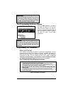
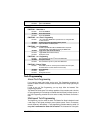
Wiring a Clutch Bypass and a
Transponder Module to the
GROUND OUT
WHEN RUNNING
wire: At the junction point,
where the GROUND OUT WHEN RUNNING wire
“splits” and connects to each device, a
diode is inserted on each of these lines.
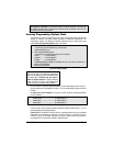
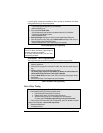
Multiple or separate Door pin Connec-
tions:
When joining all Door Pins together to the
Door Pin input wire of the Remote Car
Starter unit, each wire must be isolated with
a diode to prevent feedback.
Note: The above examples reflect common
situations where diodes are use to isolate
connections. Please note that there are
numerous other cases where diode isolation
is required.
Ƈ Always make sure that all external relays or
modules added to the Remote Car Starter
unit are properly fused and diode isolated.
Ƈ On vehicles equipped with daytime running
lights, the installer may be unable to see
certain programming results since the
daytime running lights never go out.
Note: The Parking Light Output Relay of the
unit gives two clicking sounds for each flash
of the lights: one click when the lights would
go
ON and one click when the lights would
go
OFF.)
Ƈ Parking Light flashes to which the text
refers throughout this manual refer to the
Parking Light output of the unit, not of the
vehicle.
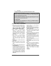
Harness Description
When connecting a Remote Car Starter, it is important to make sure that the connector with the
Ground wire is connected first, before making the 12-volt connections. Should the Unit be powered
up before being grounded, there could be serious damage to internal components of the Unit.
Be careful not to power up a Remote Car Starter before it is properly grounded. To avoid any
accident, it is recommended to pull out the Fuses from their sockets before the installation, and to
put them back during the very last steps.
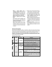
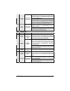
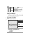
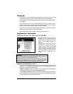
6-Pin Main Ignition Harness
Wire Colour Function Description
Connect to the largest 12 V supply wire at the Ignition Harness.
Ensure that the OEM power wire is fused for more than 30 A.
A RED (+) 12 V Battery
Please note: some of the most recent vehicles have no suitable
12 V source at the Ignition Switch (the 12 V wire is too small to
supply the necessary current). In such cases, it is recommended to
use the fuse box or the B+ connection on the Battery.
B PURPLE
(+) Starter output
(30 A)
Connect to the Starter wire of the vehicle. The source wire should
have +12 V with the Ignition Key in the
CRANK position only.
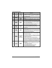
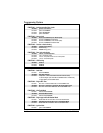
Connect to the largest 12 V supply wire at the Ignition Harness.
Ensure that the OEM power wire is fused for more than 30 A.
C RED (+) 12 V Battery
Please note: some of the most recent vehicles have no suitable
12 V source at the Ignition Switch (the 12 V wire is too small to
supply the necessary current). In such cases, it is recommended to
use the fuse box or the B+ connection on the Battery.
Connect to the Ignition wire of the vehicle. The source wire should
have +12 V with the Ignition Key in the
IGNITION ON (RUN) and
CRANK positions.
D YELLOW
(+) Ignition
output (30 A)
Warning: at the Ignition Switch of certain vehicles, there may be
more than one Ignition wire. Use the 5
th
relay (Pin F) and extra
relays to power up any extra Ignition wires if necessary. Do not
jump wires at the Ignition Switch: this would compromise the
OEM electrical system.