


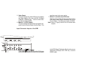
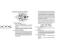


5. Video Output
This jack accepts the yellow RCA plug and applies
the video signal to the user monitor; (Example
LCM4000, LCM5600 etc.). Use the Control Sta-
tion Source Cable (CSSC).
6. Monitor 1 (12VDC Output)
This jack accepts the black barrel type power con-
nector from the Control Station Source Cable. This
supplies power to the user monitor.
7. Station 1 controller (8-pin DIN Jack)
This 8-pin jack provides the interconnection from the
SDB Audio Video Signal Distribution Box to the
Control Station. The cable part number is CSDIN.
Note: Items 4-7 apply to each of the five audio/video
outputs.
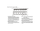
Input Connector Layout of the SDB
1. Audio Input L/R (RCA Jacks)
These jacks accept the red and white RCA plugs
from the SDBSC cable and routes the audio signals
to the SDB (Signal Distribution Box) from the source
component (Example VCP, DVD etc.). Use the
SDBSC cable.
POWER INPUT
AU DIO
1
L R
VIDEO 1 VIDEO 2 VIDEO 3 VIDEO 4
L R
AU DIO
2
L R
AUDIO
3
L R
AUDIO
4
5
IR REPEA T
TO S OURCE 1
DC 12V IR REPEATDC 12V
IR RE PEA T
TO SOURCE 3
DC 12V
IR REP EATDC 12V
3 – IGNITION
2 – CONSTANT
1 – GND
1
2
3
2
1
1
4
3
1
2
A/V SOURCE INPUT