


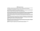
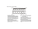
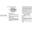

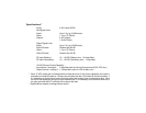
Output Connector Layout of the SDB
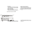
1. Audio Output L/R (RCA Jacks)
These jacks accept the red and white RCA plugs
from the Master Control Station Source Cable and
transmit the left and right audio output signals to
the FM Modulator (MCSFMM). (Note: In order to
route the signals to the modulator, a master control
station is required. The MAIN POWER button must
be pressed along with the FM POWER button on
the Master Control Station.)
2. Master Control Station Input (8-pin Din)
This 8-pin jack provides the interconnection from
the SDB Audio Video Signal Distribution Box to the
Master Control Station.
NOTE: This cable is different from the other 5-Din
cables. Be sure to use Din cable part
number MCSDIN.
3. 12VDC Output for FM Modulator
This jack accepts the black barrel type power
connector from the Master Control Station Source
Cable. This supplies power to the FM Modulator.
4. Audio Output L/R (2-RCA Jacks)
These jacks accept the red and white RCA plugs
and apply the left and right audio output signals to
the user monitor; (Example LCM4000, LCM5600
etc.). Use the Control Station Source Cable
(CSSC).
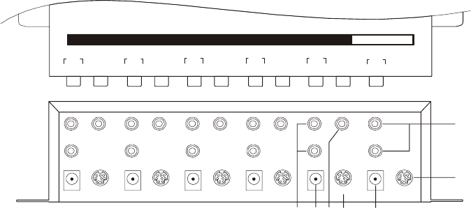
STATION 2
CONTROLLER
STATION 3
CONTROLLER
STATION 4
CONTROLLER
STATION 5
CONTROLLER
MONIT OR 5
DC 12V
STATION 1
CONTROLLER
MASTER
CONTROLLER
FM MODULATOR
DC 12V
MONIT OR 4
DC 12V
MONITOR 3
DC 12V
MONITOR 2
DC 12V
MONITOR 1
DC 12V
STATION 5
AUDIO
L R
VIDEO
STATION 4
AUDIO
L R
VIDEO VIDEO VIDEO
VIDEO
MASTER
STATION
AUDIO
L R
STATION 3
AUDIO
L R
STATION 2
AUDIO
L R
STATION 1
AUDIO
L R
AUDIO SELECT OUTPUT
1
2
37564
A/V SELECT OUTPUT