


1. Decide upon system configuration and options that
will be installed (i.e.: what components, VCP, DVD,
TV Tuner, Video Game, Monitors, etc.).
2. Review all manuals to become familiar with electri-
cal requirements and hook ups.
3. Decide upon mounting locations of all components
and method of mounting.
4. Prep the vehicle by removing any interior trim nec-
essary to gain access to vehicle’s wiring as well as
all areas where interconnecting wire harnesses will
need to be located. If any access holes need to be
cut into the vehicle (headliner, other trim components
etc.), this should be done now as well.
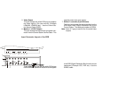
5. Route the wiring harnesses throughout the vehicle
as necessary. (Refer to the Wiring Diagram Sheet
attached as well as the wiring instructions for the
individual components and accessory options be-
ing installed). Be sure that all wiring is protected
from sharp edges and is routed in such a manner
that it will not be pinched when all components and
interior trim are fully installed. Be sure to leave
enough slack in the wiring at each component to
allow working room.
6. Remove all A/V system components from their
packaging and place them loosely in the vehicle at
their respective locations.
7. Connect all components together (electrically) and
verify proper operation of all system functions.
Note: This is best done BEFORE components have
been permanently mounted.
8. After verifying proper operation of the system,
proceed to mount each component.
9. When all components are mounted recheck the entire
system to be sure it is functioning correctly and
ensure that no wiring was pinched or connected
improperly during final installation. Use the supplied
cable clamps on the control station interconnect.
VEHICLE PREPARATION
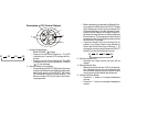
1. Locate a constant power source (+12 Vdc at all
times) and an accessory power source (+12Vdc
present when the ignition key is in the accessory
and run positions. 0Vdc should be present when
the ignition key is in the OFF position). Generally,
these wires can be found at the ignition switch or
fusebox. (NOTE: Ensure that the constant and
accessary power are fused at their sources. Failure
to do so may result in vehicle wiring damage.)
Ground the Black wire to a chassis ground close to
the mounting location of the SDB box.
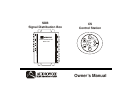
2. The mounting method and location will vary from
vehicle to vehicle, so this manual will only focus for
the installation of SDB45 A/V Signal Distribution
System in the package.
3. Generally, the best locations for SDB45 System
components are:
a) SDB Trunk
b) MCS Door pillar near driver, dashboard or
console
c) CS Door pillar near passenger or console
d) GCS Rear deck or console
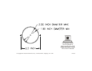
Note: A template is included at the back of this manual
for mounting the control station.
GENERAL INSTALLATION APPROACH: