


RED w/BLACK TRACE WIRE : DISARM INPUT #2
Connect this wire to the unlock side of the door lock/unlock switch or any passenger door unlock motor wire, which will
receive a negative or positive pulse when all doors are unlocked using the door panel switch or the remote transmitter,
but will not receive a pulse when the driver only door is unlocked using the remote transmitter.
BLUE WIRE : TRUNK TRIGGER SHUNT INPUT
This wire will determine if the vehicle’s trunk has been opened using the OEM transmitter, and prevent the alarm from
triggering when the transmitter is used. This wire requires a positive trigger input and must be wired to the switched +
12 volt trunk control wire from the vehicle's keyless entry unit or, the switched + 12 volt side of the vehicle's trunk release
solenoid.
WIRING THE ARM / DISARM INPUTS IN VEHICLES WITH ONE WIRE DISARM
The following represents the most common wiring routine when the vehicle's utilizes single step, (one wire) disarming.
Be certain to set selectable feature #8 to one wire disarm. Because one wire is used to disarm the alarm system, during
this mode of operation, the remote transmitter will not disarm the system during the sounding period. This also prevents
the interior door switch from disarming the unit while sounding.
GREEN WIRE: ARM INPUT
Connect this wire to the lock side of the door lock/unlock switch or the driver's door lock motor wire, which will receive
a negative or positive pulse when the doors are locked using the door panel switch or the remote transmitter.
RED WIRE : DISARM INPUT #1
Connect this wire to unlock side of the door lock/unlock switch or to any door unlock motor leg wire, which will receive
a negative or positive pulse when all doors are unlocked using the door panel switch and the remote transmitter.
RED w/BLACK TRACE WIRE : DISARM INPUT #2
Connect this wire to chassis ground.
BLUE WIRE : (+) TRUNK TRIGGER SHUNT INPUT
This wire will determine if the vehicle’s trunk has been opened using the OEM transmitter, and stop the alarm from
triggering when the transmitter is used.
Connect this wire to the + 12 volt trunk release output from the OEM Keyless Entry module.
WIRING THE ARM / DISARM INPUTS IN VEHICLES WHEN THE SYSTEM IS SET UP AS A
STAND ALONE PASSIVE (IGNITION CONTROL) ALARM SYSTEM
For this mode of operation, be certain to set selectable features #5 for passive, #7 for delay, and #8 for 1 wire disarm.
GREEN WIRE: ARM INPUT
Connect this wire to chassis ground.
RED WIRE : DISARM INPUT #1
Connect this wire to an ignition source that has +12 volts when the ignition switch is turned to the on and start positions
and has 0 volts when the switch is in any other position.
RED w/BLACK TRACE WIRE : DISARM INPUT #2
Connect this wire to chassis ground.
BLUE: TRUNK SHUNT INPUT
This wire is not used for the stand alone passive alarm application.
VALET SWITCH : Plug the 2 pin connector from the valet switch into the mating 2 pin connector on the control module.
L.E.D. : Plug the 2 pin connector from the L.E.D. into the mating 2 pin connector on the control module.
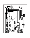
COMPLETING THE INSTALLATION
After all wire connections have been made, plug the main 14 pin connector into the control module. During the first few
seconds of power up, the circuit's processor learns the resting state of the Red, Red/Black, and Green wires of the 4 pin
connector. It is important that the ignition switch be off, and the door lock/unlock switch or transmitter not be used during
the power up sequence. Once this sequence is complete, you can disarm the system with the customers transmitter and
move onto programming the selectable features.
Page 5