


INSTALLATION OF MAJOR COMPONENTS :
ALARM CONTROL MODULE
Select a mounting location inside the passenger compartment ( up behind the dash ), and secure it using screws, or cable
ties. Do not mount the control module in the engine compartment, as it is not waterproof. Do not mount the unit or route
the wiring near the steering shaft, as it might become entangled preventing proper operation of the vehicle.
L.E.D.& VALET / OVERRIDE SWITCH ASSEMBLY
The LED & Valet/Override switch assembly are provided for to facilitate installation. The unit should be affixed to the lower
lip of the dash allowing the LED to be visible from outside the vehicle and the pushbutton switch accessible to the operator
of the vehicle.
In many installations it may be necessary or desired to separate the switch and the LED and mount these components
apart from each other. If this is the request of the customer, or the preferred method of installation, follow the information
below:
L.E.D.
The L.E.D. will serve as a visual indicator of the alarm status. It should be installed into the dashboard, located where
it is easily seen from outside the vehicle, yet not distracting to the driver. If the direct mounting is the preferred method
of installation, once a location has been selected, check behind the panel for wire routing access, and to confirm the drill
will not damage any existing components as it passes through the panel. Drill a 1/4 “ diameter hole, and pass the red
and blue wires from the L.E.D. through the hole, from the front of the panel. Firmly press the body of the L.E.D. into the
hole until fully seated.
VALET / OVERRIDE SWITCH
Select a mounting location for the valet/override pushbutton switch, that is easily accessible to the driver of the vehicle.
The switch does not have to be concealed as it cannot disarm the system without the proper programmed override code.
The valet switch may be mounted below or on the dashboard by drilling a 9/32 “ diameter hole in the selected location.
Before drilling, be sure to check the area behind the panel for adequate clearance for the body of the switch, and to be
sure that the drill will not damage any components as it passes through the panel.
SIREN
Select a mounting location in the engine compartment that is well protected from access below the vehicle. Avoid areas
near high heat components or moving parts within the engine compartment. To prevent water retention, the flared end
of the siren must be pointed downward when mounted.
Mount the siren to the selected location using the screws and bracket provided.
HOOD AND TRUNK PIN SWITCHES
Two pin switches are included for use in protecting the hood and trunk ( or hatchback ) of the vehicle.
The switches must always be mounted to a grounded, metal surface of the vehicle. It is important to select a location
where water cannot flow or collect, and to avoid all drip gutters on hood and trunk fender walls. Choose locations that
are protected by rubber gaskets when the hood or trunk lid is closed.
The pin switches can be mounted using the brackets and screws provided, or directly mounted by drilling a
1/4 “ diameter mounting hole.
Keep in mind that when properly mounted, the plunger of the pin switch should depress at least 1/4 “ when the hood or
trunk lid is closed.
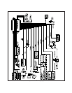
WIRING THE SYSTEM :
14 PIN CONNECTOR
RED FUSED WIRE: + 12 VDC CONSTANT BATTERY SOURCE
In all installations, the RED wire will be connected to a + 12 VDC constant battery source.
When voltage sensing, the RED wire provides power to the circuit and controls the sensitivity of the voltage sensing
circuit, which detects the turning on of an interior light when a door is opened. It will also detect the switching on of parking
or headlamps, and in many cases will trigger the alarm when a thermostatically controlled electronic cooling fan switches
on.
In voltage sensing applications, the closer to the battery that this wire is connected, the less sensitive the voltage sense
circuitry will be. Moving the connection point to the fuse panel will increase the sensitivity of the voltage sensing circuitry.
Page 2