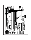
LIGHT GREEN WIRE : (-) INSTANT TRIGGER ZONE 1
This is an instant activation ground trigger wire. This wire should be reserved for connection to optional ground output
trigger devices such as motion, glass breakage and/or non plug in shock sensors.
DARK GREEN WIRE : (-) INSTANT TRIGGER ZONE 2
This is an instant activation ground trigger wire. It should be connected to the previously installed hood and trunk pin
switches.
GREEN w/BLACK TRACE WIRE : AUXILIARY OR REMOTE STARTER OUTPUT
This wire provides a low current transistorized ground pulse to control the input trigger wire of a remote starter or window
roll-up module. Connect this wire to the ground activated trigger input wire of the optional device.
2 PIN WHITE CONNECTOR : RED AND GREEN DOOR LOCK OUTPUTS (Auto Lock / Unlock)
The door lock output wires from this unit will provide control for the passive lock feature as well as ignition controlled lock
and unlock feature, and should be used only on vehicles whose Factory Keyless Entry circuits do not incorporate these
features.
These wires will provide either a pulsed ground output to the factory door lock control relay, or a pulsed +12 volt output
to the factory door lock control relay. In either case, the maximum current draw through these outputs must not exceed
300 mA.
3 Wire Ground Switched Door Locks
In this application, the red wire provides a ground pulse during the lock sequence. Connect the red wire to the wire that
provides a low current ground signal from the factory door lock switch to the factory door lock control relay.
The green wire provides a ground pulse during the unlock sequence. Connect the green wire to the wire that provides
a low current ground signal from the factory door unlock switch to the factory door unlock control relay.
3 Wire Positive Switched Door Locks
In this application, the red wire provides a positive pulse during the unlock sequence. Connect the red wire to the wire
that provides a low current positive signal from the factory door unlock switch to the factory door unlock control relay.
The green wire provides a positive pulse during the lock sequence. Connect the green wire to the wire that provides a
low current positive signal from the factory door lock switch to the factory door lock control relay.
4 Wire Polarity Reversal and
5 Wire Alternating 12 Volt
Door Lock Control Circuits
In these applications, the AS 9159 Door Lock Interface (or equivalent 30 A automotive relays) must be used. Refer to
the AUDIOVOX Door Lock Wiring Supplement for proper connection to these types of circuits.
4 PIN WHITE CONNECTOR: RED, GREEN, RED/BLACK,& BLUE FACTORY KEYLESS INPUTS:
NOTE!
When installing the PRO-9232 as a stand alone passive security system, the RED wire in this connector
must be connected to a rest at ground , + 12 VDC switched ignition source. RED w/BLACK and GREEN
wires must be connected to ground. The BLUE wire in this connector will not be required for the stand
alone installation.
The Red, Green, and Red/Black wires of the 4 pin connector are polarity learning inputs to be connected to the vehicle
unlock 1, and unlock 2 control wires. When the control circuit is first powered up, these wires will learn the resting state
of the circuits they are connected to. DO NOT operate the vehicle's door lock circuits, (switch or remote), while power
is being applied to the PRO-9232.
WIRING THE ARM / DISARM INPUTS IN VEHICLES WITH REMOTE 2 STEP UNLOCK
The following represents the most common wiring routine in vehicles using the remote 2 step unlock feature. Be certain
to set selectable feature #8 to two wire disarm.
GREEN WIRE : ARM INPUT
Connect this wire to the lock side of the door lock/unlock switch or, the driver's door lock motor leg wire, which will receive
a negative or positive pulse when the doors are locked using the door switch or the remote transmitter.
RED WIRE : DISARM INPUT #1
Connect this wire to the driver's door unlock motor wire, which will receive a negative or positive pulse when the drivers
door is unlocked with the remote transmitter, and the door switch, but does not receive a pulse when all doors are unlocked
using the remote transmitter.
Page 4


