


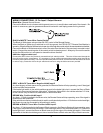
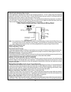

Drill a 1/4" hole in the desired location and mount the switch by passing it through the panel from the underside.
Secure the switch using the nut, star washer, and on/off face plate. It is suggested that the switch be oriented to allow
the on position to be up toward the driver and the off position to be down or away from the driver. Route the switch
wires toward the control module. Place the RED rubber boot, included in the kit, over the switch handle to differen-
tiate this switch from the program switch.
The PRO-9175FT is to be used in vehicles with AUTOMATIC TRANSMISSIONS only! Although this
combination Keyless Entry/Remote Start unit is a sophisticated system with many advanced features,
IT MUST NOT be installed into a vehicle with a manually operated transmission. Doing so may result in
serious personal injury and property damage.
IMPORTANT!
DO NOT PLUG THE SIX PIN MAIN POWER HARNESS OR THE MULTI PIN INPUT / OUTPUT HARNESS
INT O THE CONTROL MODULE UNTILALLCONNECTIONS TO THE VEHICLE HAVE BEEN MADE. AFTER
SELECTING YOURTARGET WIRESAS DEFINED BELOW, DISCONNECTTHE NEGATIVE BATTERYCABLE
FROM THE VEHICLE BATTERY PRIORTO MAKINGANY CONNECTIONS.
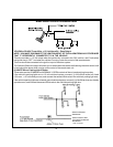
WIRING THE 6 PIN MAIN POWER HARNESS:
RED w/ WHITE Trace Wire: + 12 volt Battery 1 Source
Connect this wire toa+12VDCconstant source found at the vehicle's ignition switch using the 30 Amp fuse
and holder provided. This wire provides power for the control circuit as well as the ignition 1 and ignition 2 relays.
RED Wire: + 12 Volt Battery 2 Source
Connect this wire toa+12VDCconstant source found at the vehicle's ignition switch using the 30 Amp fuse
and holder provided, but NOT the same vehicle wire as used by the battery 1 source. Most vehicles have
more than one battery source supplying power to the ignition switch. Separate feed wires must be used for
the Red and Red/White wires. If your vehicle does not have two battery feed wires at the ignition switch then
it is possible to connect both wires to the vehicle's battery. This wire provides power for the start relay and the
accessory relay.
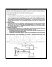
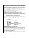
IMPORTANT!
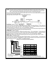
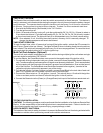
It is the responsibility of the installing technician to determine the load factor of the vehicles electrical circuits
when the vehicle is running and to adequately fuse the two power wires based on that load. If the vehicle,
running under load with the air conditioner, heater blower motor, and accessories exceed 24 Amps continu-
ous, we recommend that two fuses be used in combination on each power wire as shown below. For addi-
tional information see Tech Update issued 9/30/96.
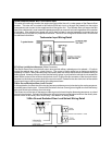
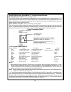
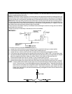
YELLOW Wire: Starter Output
Careful consideration for the connection of this wire must be made to prevent the vehicle from
starting while in gear. Understanding the difference between a mechanical and an electrical
Neutral Start Switch will allow you to properly identify the circuit and select the correct installation
method. In addition you will realize why the connection of the safety wire is required for all
mechanical switch configurations.
Failure to make this connection properly can result in personal injury and property damage.
In all installations it is the responsibility of the installing technician to test the remote start unit and assure
that the vehicle cannot start via RF control in any gear selection other than park or neutral.
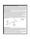
In both mechanical and electrical neutral start switch configurations, the connection of the Yellow wire will be
made to the low current start solenoid wire of the ignition switch harness. This wire will have +12 volts when
the ignition switch is turned to the start (crank) position only. This wire will have 0 volts in all other ignition
switch positions.
3