


Typically this output will be used to re-lock the vehicle doors if the doors unlock automatically when the
ignition circuit transitions to off.
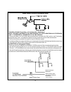
Black w/ Yellow Trace Wire: Ground Output During Start (Crank)
The Black w/ Yellow Trace wire will provide a 300 mAground output while the starter output of the remote
start unit is active. This output can be used to activate the Crank Low/Bulb Test wire found in some GM
vehicles. This wire is also referred to as the ECM wake up wire in some Chrysler vehicles.
NOTE: The outputs above are low current outputs and must be used with a relay if the circuit's requirement
is more than 300 mA.
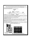
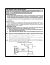
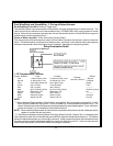
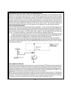
Blue and Green w/Black Trace Wires - 2 Pin Accessory Output Harness
Dark Blue Wire : Delayed 300 mA Pulsed Output/Channel 2
The dark blue wire pulses to ground via an independent RF channel from the keychain transmitter. This is
a transistorized, low current output, and should only be used to drive an external relay coil.
Thisoutputisactivatedbythesametransmitterbutton thatisusedtoactivatetheremotestartfunction(factory
defaultis button2). Press andholdbutton 2to activatethistrunk releaseoutput, orpress andreleasebutton
2 two times within 2 seconds to activate the remote starter.
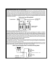
WARNING: Connecting the dark blue wire to the high current switched output of the trunk release circuits
and some remote start trigger inputs, will damage the control module.
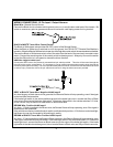
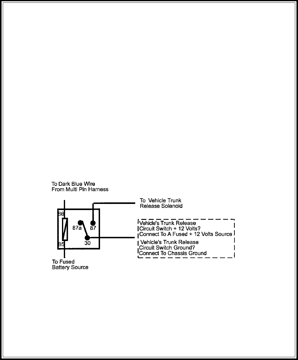
Connectthedark bluewiretoterminal86of theAS-9256relay(orequivalent30 Aautomotiverelay),connect
terminal85 toa fused+12 voltsource andwire theremaining relaycontacts toperform theselected function
of channel 2
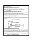
Channel 2 Relay Wiring Detail
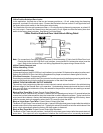
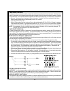
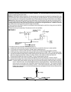
Green w/ Black Trace Wire: 300mA Latched Channel 3 Output
The Green w/ Black Trace wire supplies a 300 mA switched output whenever channel three of the receiver
is accessed. Pressing the pre-programmed transmitter button(s) will access channel three and will remain
active, for up to 8 seconds, as long as the transmitter button(s) is held. This is a low current output and
must be connected to a relay to supply power to the device you intend to control. Connect Green w/ Black
Trace wire to terminal #86 of a VF45F11 P&B relay or equivalent. Connect terminal #85 of the relay to a
fused + 12 volt source. Connect the common, normally open, and normally closed contacts of the relay to
perform the selected function of the channel 3 output.
WARNING! Connecting the dark green w/black trace wire to any high current switched output
(300 mA max.) will damage the control module.
10