


128-6199
5 of 8
Page 5
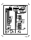
If the vehicle uses a + 12 VDC horn switch, then connect the black w/ white trace wire to terminal 86 of the AS 9256 relay (or an
equivalent 30 Amp automotive relay), and connect relay terminal 85 to a fused + 12 VDC battery source. Connect relay terminal 87
to the vehicle’s horn switch output, and connect relay terminal 30 to a fused + 12 VDC battery source.
Orange w/ White Trace Wire : 300 mA GROUND OUTPUT WHEN DISARMED - N. O. STARTER DISABLE ( Optional Relay
Required ).
This wire is provided to control the starter cut relay. Connect the orange w/white wire to terminal 86 of the relay. Connect relay
terminal 85 to an ignition wire in the vehicle that is live when the key is in the on and crank positions, and off when the key is in
the off position. (This is where the yellow wire from the alarm should also be connected).
Cut the low current starter solenoid wire in the vehicle, and connect one side of the cut wire to relay terminal 87. Connect the
other side of the cut wire to relay terminal 30.
Note : This is a normally opened starter cut arrangement, and when power is removed from the security
system, the starter disable feature will remain operational, and the vehicle will not start. Audiovox
does not recommend using the Orange w/ White trace wire to interrupt anything but the starting circuit
of the vehicle.
Dark Green w/ Black Trace Wire : Latching Output / Channel 4
This wire latches to ground via an independent RF channel from the keychain transmitter. This is a transistorized, low current
(300 mA) output, and should only be used to drive an external relay coil.
This wire provides an immediate ground signal, and stays at ground for up to 8 seconds, as long as the button(s) on the
keychain transmitter remain pressed, providing the ignition is off or all doors are closed.
CAUTION ! Connecting this wire to any high current circuits will damage the control module.
Connect this output to terminal 86 of the AS 9256 relay ( or an equivalent 30 Amp automotive relay ), and wire the remaining relay
contacts to perform the selected function of channel 4.
Light Blue w/Green Trace Wire: Channel 5 Output
This wire provides a pulsed or switched output which operates when the programmed transmitter button is pressed and
released or pressed and held, for up to 8 seconds. This output also has the ability to operate with the ignition on providing the
transmitter is pressed twice, or pressed twice and held. The output in these instances will be the same as above, pulsed when
pressed twice and released, switched for up to 8 seconds when the transmitter button is pressed twice and held. This is a
transistorized, low current ( 300 mA ) output, and should only be used to drive an external relay coil.
CAUTION ! Connecting this wire to any high current circuits will damage the control module.
Connect this output to terminal 86 of the AS 9256 relay (or an equivalent 30 Amp automotive relay), and wire the remaining relay
contacts to perform the selected function of channel 5.
Dark Green Wire : ( - ) INSTANT TRIGGER ZONE 2
This is an instant on ground trigger wire. It must be connected to the previously installed hood and trunk pin switches.
Purple Wire : + DOOR TRIGGER
If the vehicle’s door courtesy light switches have a + 12 volt output when the door is opened (most Fords and some Imports),
you must connect this wire to the positive output from one of the door switches. In most cases, the purple wire will only need
to be connected to one door switch, no matter how many doors the vehicle has.
CAUTION : Do not use the purple wire if the vehicle has ground output type door switches.
(see Brown Wire).
Brown Wire : - DOOR TRIGGER
If the vehicle’s courtesy light switches have a ( - ) ground output when the door is opened (GM and most Imports), you must
connect this wire to the negative output from one of the door switches.
WARNING : Do not use the brown wire if the vehicle has + 12 volt output type door switches. (see Purple Wire).
Light Green Wire : ( - ) Instant Trigger Zone 1
This is an instant on ground trigger wire. This wire (zone) should be reserved for connection to optional ground output trigger
devices such as motion and / or shock impact sensors.
3 Pin Antenna/Receiver Connector:
Plug the previously routed three pin connector from the antenna receiver assemble into the mating connector of the control
module. This connector supplies 12 volts, ground and RF data from the antenna receiver to the remote start module. Be certain
this connector is firmly seated making good contact to the control unit.