


128-6199
3 of 8
The valet switch can be mounted to the lower side of the dash by drilling a ¼ " diameter hole in the selected location.
Be sure to check behind the dash for adequate clearance for the body of the switch, and to confirm that the drill will not damage
any existing components as it passes through the dash. You should also make certain that the back of the switch is accessible
for wiring later in the installation.
Shock Sensor :
Select a solid mounting surface for the shock sensor on the firewall inside the passenger compartment, and mount the
sensor using the two screws provided. The shock sensor can also be secured to any fixed brace behind the dash using tie straps.
Whichever mounting method is selected, make certain that the sensitivity adjustment is accessible for use later in the installation.
THE RECEIVER/ANTENNA ASSEMBLY:
The Superheterodyne Receiver Antenna Assembly provided with this unit allows routing from below the dash board for
maximum operating range. Choose a location above the belt line (dashboard) of the vehicle for best reception. Special
considerations must be made for windshield glass as some newer vehicles utilize a metallic shielded window glass that will
inhibit or restrict RF reception. In these vehicles, route the antenna toward a rear window location for best reception. Secure
the antenna with double stick tape provided. After securing the antenna with tape, we advise also securing a section of the
antenna cable to a fixed support. This will prevent the antenna from dropping down in case the double stick tape is exposed
to extreme heat which may loosen it's gummed surface. Route the 3 pin connector toward the control module using caution not
to pinch the cable as this will cause poor or no RF reception to the control module.
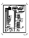
WIRING THE SYSTEM
Large 9 Pin Edge Connector :
Red Fused Wire : + 12 VDC CONSTANT BATTERY SOURCE
This wire controls the sensitivity of the voltage sensing circuit, which detects the turning on of an interior light when a door is
opened. It will also detect the switching on of parking or headlamps, and in many cases will trigger the alarm when a
thermostatically controlled electronic radiator cooling fan switches on.
When installing this system into vehicles with electronic “ after fans “, it is recommended you disable the voltage sense circuit.
In voltage sensing applications, the closer to the battery that the red wire is connected, the less sensitive the voltage sense
circuitry will be. Moving this connection point to the fuse panel will increase the sensitivity, and connecting to the courtesy lamp
fuse in the vehicle will provide maximum sensitivity of the voltage sense circuit.
When hardwiring the control module to pin switches at all entry points, the voltage sense circuit must be disabled. Set
programmable feature # 6 to the voltage sense "OFF" position, 2 chirps, then connect the red wire to a + 12 VDC constant battery
source.
White Wire : + 12 VDC PULSED PARKING LIGHT OUTPUT ( 15 AMP MAX )
This wire is provided to flash the vehicle’s parking lights. Connect the white wire to the positive side of one of the vehicle’s
parking lights.
Yellow Wire : + 12 VDC IGNITION SOURCE
Connect this wire to a source that is live when the key is in the on and crank positions. Be sure that this source is off when the
key is in the off position.
White w/ Black Trace Wire : POSITIVE OUTPUT TO SIREN
Route this wire through a rubber grommet in the firewall, and to the siren location. Connect the white / black wire to the positive wire
of the siren. Secure the black ground wire of the siren to chassis ground.
Black Wire : CHASSIS GROUND
Connect this wire to a solid, clean, metal part of the vehicle’s chassis.
Dark Blue w/Black Trace Wire: Alternate Channel 3 Output (Dbl. Push Required)
This wire is controlled from the transmitter button programmed to the receiver's channel 3. By double pressing this the
transmitter button, this output will become active for 1 second. This is a transistorized, low current ( 300 mA ) output, designed
to provide an output only when the transmitter is intentionally operated, such as is the case with remote start add on modules.
If you require more than 300mA drive from this output, you must drive an external relay coil, and arrange the relays contacts
to preform the specified function.
Page 3