


Page 5
it into the mating blue connector on the side of the module.
2 Pin White Connector : DASH MOUNTED L.E.D.
Route the red and blue wires in the 2 pin white connector from the L.E.D. to the control module, and plug
it into the mating white connector on the side of the module.
4 Pin White Connector : SHOCK SENSOR
Route the red, black, blue, and green wires in the 4 pin white connector from the shock sensor to the
control module, and plug one end into the shock sensor, and the other end into the mating white connector
on the side of the module.
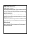
Red & Green 2 Pin White Connector : DOOR LOCK OUTPUTS
These wires will provide either a pulsed ground output to the factory door lock control relay, or a pulsed +
12 volt output to the factory door lock control relay. In either case, the maximum current draw through
these outputs must not exceed 300 mA.
3 Wire Ground Switched Door Locks
In this application, the red wire provides a ground pulse during arming, or the pulsed ground lock output.
Connect the red wire to the wire that provides a low current ground signal from the factory door lock switch
to the factory door lock control relay.
The green wire provides a ground pulse during disarming, or the pulsed ground unlock output. Connect
the green wire to the wire that provides a low current ground signal from the factory door unlock switch to
the factory door lock control relay.
3 Wire Positive Switched Door Locks
In this application, the red wire provides a positive pulse during disarming, or the pulsed + 12 volt unlock
output. Connect the red wire to the wire that provides a low current positive signal from the factory door
unlock switch to the factory door lock control relay.
The green wire provides a positive pulse during arming, or the pulsed + 12 volt lock output. Connect the
green wire to the wire that provides a low current positive signal from the factory door lock switch to the
factory door lock control relay.
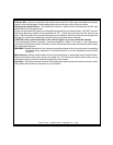
4 Wire Polarity Reversal and
5 Wire Alternating 12 Volt
Door Lock Control Circuits
In these applications, the AS 9159 Door Lock Interface ( or equivalent 30 A automotive relays ) must be
used. Refer to the AUDIOVOX Door Lock Wiring Supplement for proper connection to these types of
circuits.
COMPLETING THE INSTALLATION