


Page 4
If the vehicle’s courtesy light switches havea(-)ground output when the door is opened ( GM and most
Imports ), you must connect this wire to the negative output from one of the door switches.
WARNING : Do not use the brown wire if the vehicle has + 12 volt output type door switches. ( see Purple
Wire ).
Dark Green Wire : ( - ) INSTANT TRIGGER ZONE 2
This is an instant on ground trigger wire. It must be connected to the previously installed hood and trunk pin
switches.
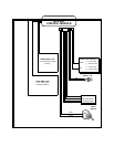
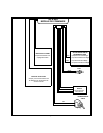
Orange w/ White Trace Wire : 300 mA GROUND OUTPUT WHEN DISARMED - N. O. STARTER
DISABLE ( Optional Relay Required ).
This wire is provided to control the starter cut relay. Connect the orange w/white wire to terminal 86 of the
relay. Connect relay terminal 85 to an ignition wire in the vehicle that is live when the key is in the on and
crank positions, and off when the key is in the off position. ( This is where the yellow wire from the alarm
should be connected ).
Cut the low current starter solenoid wire in the vehicle, and connect one side of the cut wire to relay
terminal 87. Connect the other side of the cut wire to relay terminal 30.
Note : This is a normally opened starter cut arrangement, and when power is removed from the
security system, the starter disable feature will remain operational, and the vehicle will
not start. Audiovox does not recommend using the Orange w/ White trace wire to inter-
rupt anything but the starting circuit of the vehicle.
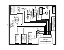
White w/ Black Trace Wire : POSITIVE OUTPUT TO SIREN
Route this wire through a rubber grommet in the firewall, and to the siren location.
Connect the white / black wire to the positive wire of the siren. Secure the black ground wire of the siren to
chassis ground.
Dark Green w/ Black Trace Wire : LATCHING OUTPUT / CHANNEL 3
The green w/ black trace wire latches to ground via an independant RF channel from the keychain transmit-
ter. This is a transistorized, low current ( 300 mA ) output, and should only be used to drive an external
relay coil.
This wire provides an immediate ground signal, and stays at ground for as long as the button(s) on the
keychain transmitter remain pressed.
WARNING ! Connecting the dark green w/ black trace wire to the high current switched output of
trunk release circuits will damage the control module.
Connect the dark green w/ black trace wire to terminal 86 of the AS 9256 relay ( or an equivalent 30 Amp
automotive relay ), and wire the remaining relay contacts to perform the selected function of channel 3.
Dark Blue Wire : DELAYED 300 mA PULSED OUTPUT / CHANNEL 2
The dark blue wire pulses to ground via an independent RF channel from the keychain transmitter. This is
a transistorized, low current output, and should only be used to drive an external relay coil.
WARNING: Connecting the dark blue wire to the high current switched output of trunk release circuits,
some remote start trigger inputs, will damage the control module.
Connect the dark blue wire to terminal 86 of the AS - 9256 relay (or equivalent 30 A automotive relay), and
wire the remaining relay contacts to perform the selected function of channel 2.
2 Pin Blue Connector : VALET SWITCH
Route the grey and black wires in the 2 pin connector from the valet switch to the control module, and plug