


Page 3
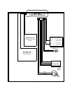
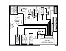
WIRING THE SYSTEM
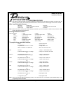
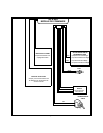
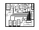
Large 13 Pin Edge Connector :
Red Fused Wire : + 12 VDC CONSTANT BATTERY SOURCE
This wire controls the sensitivity of the voltage sensing circuit, which detects the turning on of an interior
light when a door is opened. It will also detect the switching on of parking or headlamps, and in many
cases will trigger the alarm when a thermostatically controled electronic radiator cooling fan switches on.
When installing this system into vehicles with electronic “ after fans “, it is recommended you disable the
voltage sense circuit.
In voltage sensing applications, the closer to the battery that the red wire is connected, the less sensitive
the voltage sense circuitry will be. Moving this connection point to the fuse panel will increase the sensitiv-
ity, and connecting to the courtesy lamp fuse in the vehicle will provide maximum sensitivity of the voltage
sense circuit.
When hardwiring the control module to pin switches at all entry points, the voltage sense circuit must be
disabled. Cut the Green wire loop, then connect the red wire toa+12VDCconstant battery source.
Orange Wire: 300 mA GROUND OUTPUT WHEN ARMED - N. C. STARTER DISABLE (Optional Relay
Required)
This wire is provided to control the starter cut relay. Connect the orange wire to terminal 86 of the relay.
Connect relay terminal 85 to an ignition wire in the vehicle that is live when the key is in the on and crank
positions, and off when the key is in the off position. ( This is where the yellow wire from the alarm should
be connected ).
Cut the low current starter solenoid wire in the vehicle, and connect one side of the cut wire to relay
terminal 87A. Connect the other side of the cut wire to relay terminal 30.
Note : This is a normally closed starter cut arrangement, and when power is removed from the
security system, the starter disable feature will not operate, allowing the vehicle to start.
Audiovox does not recommend using the Orange wire to interrupt anything but the start-
ing circuit of the vehicle.
Black Wire : CHASSIS GROUND
Connect this wire to a solid, metal part of the vehicle’s chassis. Do not confuse this wire with the thin black
antenna wire that exits the control module independantly.
White Wire : + 12 VDC PULSED PARKING LIGHT OUTPUT ( 15 AMP MAX )
This wire is provided to flash the vehicle’s parking lights. Connect the white wire to the positive side of one
of the vehicle’s parking lights.
Yellow Wire : + 12 VDC IGNITION SOURCE
Connect this wire to a source that is live when the key is in the on and crank positions. Be sure that this
source is off when the key is in the off position.
Purple Wire : + DOOR TRIGGER
If the vehicle’s door courtesy light switches havea+12volt output when the door is opened ( most Fords
and some Imports ), you must connect this wire to the positive output from one of the door switches. In
most cases, the purple wire will only need to be connected to one door switch, no matter how many doors
the vehicle has.
WARNING : Do not use the purple wire if the vehicle has ground output type door switches. ( see Brown
Wire ).
Brown Wire : - DOOR TRIGGER