


128-7760
8 of 16
8
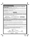
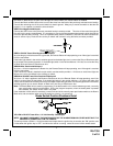
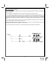
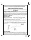
Tachometer Input Wiring Detail
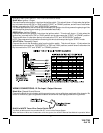
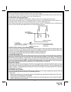
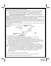
WIRING THE 4 PIN AUXILIARY OUTPUT HARNESS
The auxiliary 4 pin connector provides low current outputs to control various functions in the vehicle during different
stages of the Remote Start unit's operation. Understanding these outputs and the time in which they occur will
allow you to determine if they are needed for the particular vehicle you are working on as well as how to use them.
Black w/ Blue Trace Wire: Pulsed Ground Output Before Start
The Black w/ Blue Trace wire will provide a 1 second 300 mA pulsed ground output 1.5 second before the remote
start unit activates as well as when the transmitter is used to unlock/disarm the system. Typical use for this output
would be to disarm a factory theft deterrent system to prevent false triggering of the factory alarm when the remote
start unit engages.
Black w/ Light Green Trace Wire: Pulsed Ground Output After Start
The Black w/ Light Green Trace wire will provide a 1 second 300mA pulsed ground output after the vehicle is
started under control of the remote start unit. Typically this wire will be used to re-lock the vehicle doors if the doors
unlock automatically when the factory anti-theft system is disarmed.
Black w/ Red Trace Wire: Pulsed Ground Output After Shutdown
The Black w/ Red Trace wire will provide a 1 second 300 mA pulsed ground output after the remote start unit shuts
down. This output will occur regardless of whether the circuit times out or is manually terminated. Typically this
output will be used to re-lock the vehicle doors if the doors unlock automatically when the ignition circuit transitions
to off.
Black w/ Yellow Trace Wire: Ground Output During Start (Crank)
The Black w/ Yellow Trace wire will provide a 300 mA ground output while the starter output of the remote start unit
is active. This output can be used to activate the Crank Low/Bulb Test wire found in some GM vehicles. This wire
is also referred to as the ECM wake up wire in some Chrysler vehicles.
NOTE: The outputs above are low current outputs and must be used with a relay if the circuit's requirement is more
than 300 mA.
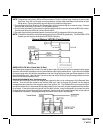
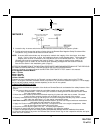
4 PIN KEYLESS ENTRY UPGRADE INPUT TRIGGER WIRES:
The system allows the factory keyless entry units to directly trigger the remote start providing the factory system
sequentially unlocks, first the drivers door, then the passenger doors if the transmitter is activated a second time.
The Red, Green, and Red/Black wires when properly connected and sequentially operated, lock, unlock, lock,
trigger the remote start unit. While the vehicle is operating under command of the remote start unit, if the lock,
unlock, lock buttons are sequentially activated the remote start will shut down. Because these wires learn the
polarity of the vehicles door lock system, it is necessary, that the Red, Red/Black, and Green wires be connected
before connecting the main 6-pin and 12-pin connectors to the control module.
TO OPERATE THIS UNIT DIRECTLY FROM THE FACTORY KEYLESS CONNECT AS FOLLOWS:
RED Wire: Driver Door Unlock
Connect the Red wire of the three pin connector to the driver's door unlock motor leg.
GREEN Wire: Door Lock Wire
Connect the Green wire of the three pin connector to the driver's door lock motor leg.
RED/BLACK Wire: Unlock Switch Or Passenger Motor Unlock Wire
Connect the Red/Black wire of the three pin connector to the unlock wire of the door lock control switch.
Connect the Main 12 pin and 6-pin connectors.
DARK BLUE/BLACK TRACE Wire: Trigger Input
The Dark Blue/Black trace wire is the trigger input wire. When this wire receives a pulse ground from the
controlling remote circuit, the remote start unit to activate. Connect this wire to a ground pulsed output from
the controlling circuit. (When upgrading a factory keyless entry system, do not use this wire. See information
concerning the 3 pin upgrade connector found later in this manual)
NOTE:If you are not upgrading a factory keyless entry system and these wires are not used, all three wires MUST
BE connected to chassis ground. (See Dark Blue/Black Wire for single trigger input.)