


128-7760
4 of 16
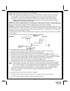
4
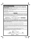
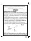
SEE NEUTRAL START SAFETY TEST FOR FURTHER DETAILS.
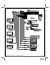
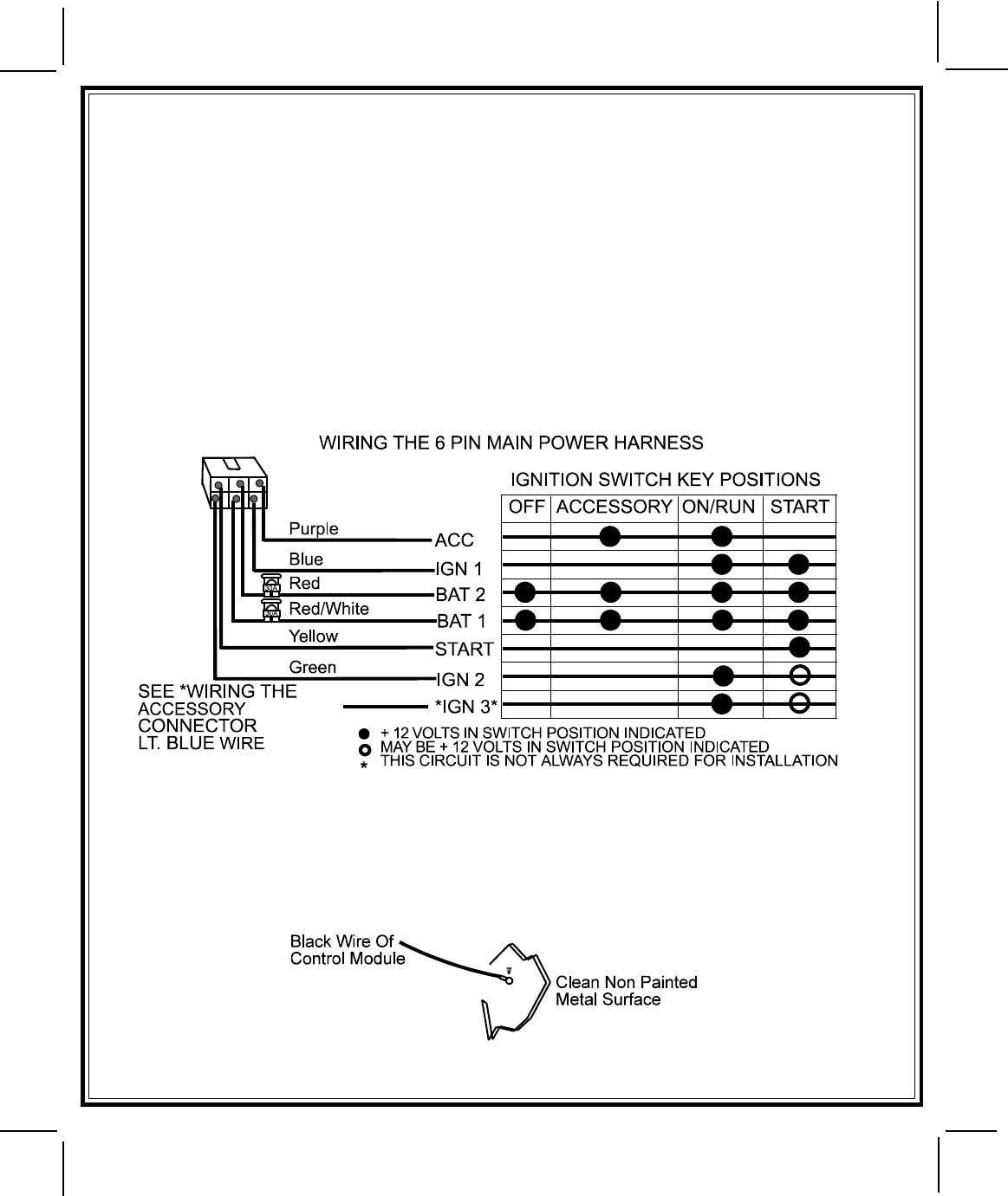
BLUE Wire: Ignition 1 Output
Connect this wire to the ignition 1 wire from the ignition switch. This wire will show +12 volts when the ignition
key is turned to the to the "ON" or "RUN" and the "START" or CRANK" positions, and will have 0 volts when
the key is turned to the "OFF" and "ACCESSORY" positions.
For Diesel Applications, this wire must be connected to the ignition circuit that powers the glow plugs if the
vehicle requires glow plug pre-heating. (See selectable feature #5)
GREEN Wire: Ignition 2 Output
Connect this wire to the ignition 2 wire from the ignition switch. This wire will show + 12 volts when the
ignition key is turned to the "ON" or "RUN" position and is some cases the "START" or CRANK" position.
This wire will show 0 volts when the key is turned to the "OFF" and "ACCESSORY" positions.
NOTE: See programming information concerning this wire to allow output during the "START" mode.
VIOLET Wire: Accessory Output
Connect this wire to the Accessory wire from the ignition switch. This wire will show + 12 volts when the
ignition switch is turned to the "ACCESSORY" or "ON" and "RUN" positions, and will show 0 volts when the
key is turned to the "OFF" and "START" or "CRANK" positions.
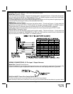
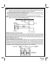
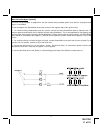
WIRING CONNECTIONS: 12 Pin Input / Output Harness
Black Wire: Chassis Ground Source
Connect the Black wire to a known vehicle ground source or to a solid clean metal part of the chassis. Be
certain to remove any paint or grease and secure this wire with a self taping screw and ring terminal.
BLACK w/WHITE Tracer Wire: Control Switch
The Black w/ White tracer wire provides ON-OFF control of the Remote Starter.
When the Black w/ White wire is switched to a full time ground, the AS-9075 Remote Start Module is operative. When