


128-7760
5 of 16
5
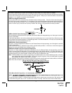
the Black w/ White wire is at open circuit through the control switch, the remote starter is disabled.
Connect the Black w/ White tracer wire to one of the wires from the back of the previously mounted control switch.
Connect the remaining wire of the control switch to chassis ground. Always try to mount the switch so that the ON
position is in an upward or toward the driver direction.
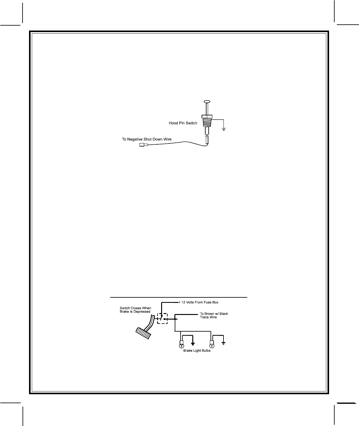
GREY Wire: Negative Inhibit Input 1
Connect the GREY wire to the previously mounted hood pin switch provided . This wire will be routed through the
fire wall into the engine compartment. It is necessary to use an existing grommet when passing wires through the
fire wall to prevent short circuiting. This is an important safety feature of AS-9075, and failure to use this feature can
result in serious injury. Route the wire to the pin switch and connect it using the bullet connector provided.
GREY w/ BLACK Tracer Wire: Negative Inhibit Input 2
Any time the grey w/ black tracer wire is grounded, the Remote Starter will stop operating, even if the signal is received
from the transmitter.
If the brake light switch in the vehicle switches ground to the brake light circuit, connect the Grey w/ Black trace wire
to the output of the brake light switch. If the brake light switch in the vehicle switches +12 Volts, do not use the Grey
w/ Black wire; see Brown w/ Black tracer wire.
BROWN Wire: Positive Inhibit Input 1
Any time + 12 Volts is applied to the Brown wire, the Remote Starter will stop operating, even if the signal is received
from the transmitter.
If the vehicle has a factory installed hood pin switch, and that switch provides + 12 Volts to an under hood light, the
Brown wire can be connected to the existing pin switch.
BROWN w/ BLACK Tracer Wire: Positive Inhibit Input 2
Any time + 12 Volts is applied to the Brown w/ Black tracer wire, the Remote Starter will stop operating, even if the
signal is received from the transmitter. If the brake light switch in the vehicle switches + 12 Volts to the brake light
circuit, connect the Brown w/ Black trace wire to the output of the brake light switch. If the brake light switch in the vehicle
switches ground, do not use the Brown w/ Black wire; see Grey w/ Black tracer wire.
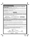
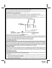
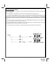
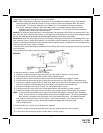
Note: The Brown/Black wire is used for programming, if the brake switch in the vehicle switches ground, a normally
open push-button switch must be added. During the program sequence, when the brake pedal is pressed
and released, this switch will be used in it's place.
If the installation of this switch is necessary, connect one end of the normally open push button switch to the Brown/
Black wire, and connect the other end of the switch to a fused + 12 volt source.
Brake Switch Positive Shutdown Detail
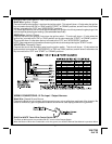
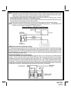
YELLOW w/ BLACK Tracer Wire: + 12 Volt Alarm By - Pass Output
NOTE: YOU MUST DISCONNECT THE IGNITION INPUT OF THE ALARM FROM ANY OTHER WIRE THAT IT IS
PRESENTLY CONNECTED TO IN THE VEHICLE.
This wire provides a 500mA + 12 Volt transistorized output when the ignition key is turned to the “ON” position, and
0 Volts when the ignition key is “OFF” and when the vehicle is running under the control of the remote starter.