


Page 4
50f19
2 DARK BLUE WIRES: PULSED OUTPUT / CHANNEL 2 (TRUNK RELEASE)
The dark blue wires are controlled via an independent RF channel from the keychain transmitter. These are the NO and
COMMON contacts of an on board, 10 A relay, so they can be connected to positive or negative switched circuits.
Connect one of the dark blue wires to the output of the trunk release pushbutton switch, and the other dark blue wire to
either chassis ground, or + 12 VDC battery, depending on the polarity of the trunk release circuit in the vehicle.
When using this channel for an accessory other than trunk release, connect one dark blue wire to the accessory, and
the otherdark blue wireto either chassisground, or, toa fused +12 volt batterysource, depending uponthe requirements
of the accessory.
WARNING:Neverattempttopullmorethan10Amperes ofcurrentthroughthisrelay.Thecircuitwillbedamaged.
Always check the requirements of accessories prior to connecting them to the circuit.
ANTENNA WIRE: Be sure to extend the thin blackantenna wire to its full length, and cable tie into placewhere it cannot
be damaged. Avoid wrapping this wire around major, high current wire looms.
WIRE DRESSING: Always wrap the alarm wires in convoluted tubing, or with a spiral wrap of electrical tape. Secure
these looms along the routing using cable ties.
This will ensure that the alarm wires are not damaged by falling onto hot or sharp moving surfaces in the vehicle.
OPERATION: Take a few moments to check off the appropriate option boxes in the owner’s manual, and to fully explain
the operation of the system to your customer.
GREY & BLACK 2 PIN (blue) CONNECTOR: VALET SWITCH
Route the two conductor, blue connector from the valet switch to the alarm control module, and plug it into the mating
blue connector on the end of the module.
RED & BLUE WIRES: DASH MOUNTED L.E.D.
Route the two conductor, white connector (red and blue wires) from the L.E.D. to the alarm control module, and plug it
into the mating white connector on the end of the module.
6 PIN DOOR LOCK OUTPUT CONNECTOR:
The orange, blue w/white tracer, yellow, white, green, and blue wires in the 6 conductor connector are the contacts of the
on board door lock relays. The function of each of these wires is listed below;
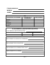
LOCK RELAY:
orange=N.O. relay contact
dark blue=N.C. relay contact
white=common relay contact
blue/white tracer=N.O. relay contact
dark green=N.C. relay contact
yellow=common relay contact
UNLOCK RELAY:
3 WIRE GROUND SWITCHED DOOR LOCK CIRCUITS:
In these vehicles, the dark green and dark blue door lock wires are not used.
The orange and blue w/white stripe wires must be connected to a chassis ground source.
The yellow wire is the ground pulse "lock" output, and should be connected to the negative lock wire in the vehicle.
The white wire is the ground pulse "unlock" output, and should be connected to the negative unlock wire in the
vehicle.
3 WIRE POSITIVE SWITCHED DOOR LOCK CIRCUITS:
In these vehicles, the dark green and dark blue door lock wires are not used.
The orange and blue w/white stripe wires must be connected to a +12 volt battery source.
The yellow wire is the positive pulse "lock" output, and should be connected to the positive lock wire in the vehicle.
The white wire is the positive pulse "unlock" output, and should be connected to the positive unlock wire in the vehicle.
5 WIRE ALTERNATING DOOR LOCK CIRCUITS:
In this application, it is necessary to cut the existing door lock by pass wires. These wires run from the master door lock
switch to the slave door lock switch, and then on to the door lock motors.
Cut the existing lock wire, and connect the yellow wire to the slave switch or motor side of the cut wire. Connect the green
wire to the master switch side of the cut wire.
Cut the existing unlock wire, and connect the white wire to the slave switch or motor side of the cut wire. Connect the
blue wire to the master switch side of the cut wire.
The orange and blue w/white stripe wires must be connected to a fused +12 VDC battery source.
Refer to the AUDIOVOX Door Lock Wiring Supplement for proper connection of these wires into the various locking
circuits available in current vehicles.
COMPLETING THE INSTALLATION: