


DOOR LOCK / UNLOCK OUTPUTS:
This system provides on-board door lock and unlock relays, making it directly compatible with most original equipment
door lock circuits used in today's vehicles.
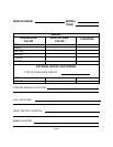
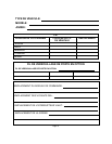
FUTURE REFERENCE CHART:
As an added convenience to the professional security installer, a chart has been printed in this guide for recording wire
colors, component mounting locations, and any other useful tips particular to the vehicle you are working on. Taking a
few extra moments on each installation to fill in the chart, can save you valuable time in the future.
TRANSMITTER PROGRAMMING:
The transmitters included in this kit have been programmed at the factory for the Channel 1 (arm, disarm and panic
function) only. Any additional functions of the system (receiver Channels 2 and 3) must be programmed at the time of
installation. These functions can be assigned to transmitter button number 2, or a simultaneous press of both buttons
1 and 2.
Refer to the transmitter programming guide, included in this package, for more details regarding transmitter button
assignments and system functions.
Page 2
VALET SWITCH:
Select a desired mounting location for the switch, that is easily accessible to the driver of the vehicle.
The switch does not have to be concealed, however, concealing the switch is always recommended, as this provides an
evenhigherlevel ofsecurityto thevehicle.Theswitch maybemounted belowthedash usingoneofthe bracketsprovided,
or mounted in the dash by drilling a 1/4" diameter hole in the location. Be sure to check behind the dash for adequate
clearance for the body of the switch, and to confirm that the drill will not damage any existing components as it passes
through the dash.
Whichever mounting method is used, make certain the back of the switch is accessible for wiring later in the installation.
DASH MOUNTED L.E.D.:
A small red L.E.D. is included that will serve as a visual indicator of the alarm status. It should be installed in the dash,
located where it can be easily seen from outside the vehicle, yet not be distracting to the driver.
Once alocation has beenselected, check behindthe panel forwire routing access, andto confirm thedrill will notdamage
any existing components as it passes through the panel.
Drill a 15/64" diameter hole, and pass the red and blue wires from the L.E.D. through the hole, from the front of the panel.
Firmly press the body of the L.E.D. into the hole until fully seated.
HOOD OR TRUNK PIN SWITCH:
A pin switch is included for use in protecting the hood or trunk (or hatchback) of the vehicle.
The switch must always be mounted to a grounded, metal surface of the vehicle. It is important to select a location where
water cannot flow or collect, and to avoid all drip “gutters” on hood and trunk fender walls. Choose locations that are
protected by rubber gaskets when the hood or trunk lid is closed.
The pin switch can be mounted using the bracket provided, or direct mounted by drilling a 9/32" diameter mounting hole.
Keep in mind that when properly mounted, the plunger of the pin switch should depress at least 1/4" when the hood or
trunk lid is closed.
CONTROL MODULE:
Select a mounting location inside the passenger compartment (up behind the dash), and secure using two screws
provided.
The control module can also be secured in place using cable ties.
Do not mount the control module in the engine compartment, as it is not waterproof. You should also avoid mounting the
unit directly onto factory installed electronic components. These components may cause RF interference, which can
result in poor transmitter range or intermittent operation.
SIREN:
Select a mounting location in the engine compartment that is well protected from access below the vehicle. Avoid areas
near high heat components or moving parts within the engine compartment. To prevent water retention, the flared end
of the siren must be pointed downward when mounted.
Mount the siren to the selected location using the screws and bracket provided.
INSTALLATION OF MAJOR COMPONENTS: