


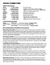

Recommended Installation Procedures
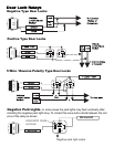
White (+) Park lights Park light output.
Orange (-) When Armed Negative output when system is armed.
Grey (-) Trunk Release Negative output for trunk release. 500ma max.
Yellow Ignition Input Input from vehicles ignition wire.
RedMain Power Input Constant 12 Volt input.
Brown (+) Siren Output Positive output for siren.
Black Ground Input System ground input.
Purple (+) Door Input Positive door pin switch input.
Green (-) Door Input Negative door pin switch input.
Blue (-) Hood Input Negative input from hood pin switch.
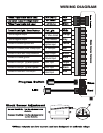
10 Pin Connector
Green Door Lock Door Lock Output - *Programmable
12 Volt Output Output for voltage inverter. Low Current Only
Blue Door Unlock Door Unlock Output - *Programmable
3 Pin Connector Red
Under Hood Connections- Route the hood pin (optional) and Siren wire through the
firewall, into the engine compartment. Always try to pull the wires through a factory rubber
grommet. If drilling through the firewall, BE CAREFUL. Check for obstructions on both sides
of the firewall. After drilling use a snap in grommet to protect the wires from sharp edges.
Mounting the module- Never mount the module in the engine compartment. Select a
location under the dash to install the main module. Be certain that the module is securely
attached and does not obstruct any serviceable areas. Mount the module so that it cannot
be seen if looking under the dash as it could be easily unplugged by a thief. The module
must be free from all moving parts.
Mounting the Siren- Choose a location in the engine compartment that is away from
high heat sources and direct exposer to water. The siren should be mounted as well as
grounded to solid metal. Run the wiring for the siren so that it can not be seen or reached
from below the vehicle.
Installing the LED- Choose a location that will be highly visible when the LED is installed.
Most vehicles are equipped with knock out panels in the dashboard, these panels are easily
removable and can be easily replaced if necessary. Once the location is picked, use drill bit
and drill a hole through the panel. Test fit the LED into the hole. Plug the Led into the Red
connector on the main module.
Installing the Program Button- Choose a location to mount the Program Button. This
location should be hidden and not visible from outside the vehicle. Once the location of the
switch is picked, use a 1/4” drill bit and drill a hole. Remove the nut and push the Program
Button through the hole. Replace the nut and tighten until the switch is secure. Plug the
Program Button into the Blue connector of the main module.