


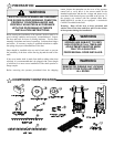
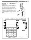
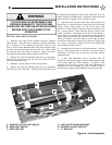
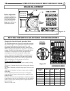

A - REVERSE CUTOUT LIMIT SWITCH
B - OPEN LIMIT SWITCH
C - OPEN LIMIT NUT
D - LIMIT NUT RETAINING BRACKET
E - REVERSE CUTOUT LIMIT NUT
F - “V” BRACKET
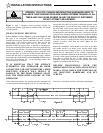
SETTING THE LIMIT SWITCHES
1) With the cover open on the electrical enclosure, reference
Figure 6 below. There are two (2) switches (A and B) mounted to
the ‘V’ bracket (F). The switches are activated by the two limit
nuts (C and E) on the threaded shaft which move laterally along
the shaft as the operator opens and closes the door. When a limit
nut nears the end of the shaft it activates a switch, that send a
message back to the motor control board to stop the door.
2) Depress the Limit Nut Retention Plate (D) so it disengages
from the slots in the limit nuts and move the Limit nuts to the
center of the threaded shaft.
3) Manually raise the door to a nearly open position.
4) Depress the limit nut retaining plate (D) so it disengages
from the slots in the limit nuts. Turn the OPEN limit nut (C) on
the shaft until it engages the Open Limit Switch (B). You will
need to listen for an audible click. Release the retaining bracket
and be sure that it engages in slots of both limit nuts.
5) Manually lower the door to the fully closed position and
repeat Step #3 with the Reverse Cutout Limit nut (E) and the
Reverse Cutout Limit switch (A). The actual Close Limit
position is a timed function whereas the door continues to run
for a certain period of time after the Reverse Cutout Limit
switch is activated. This amount of time (Close Limit Delay) is
factory set to 0.32 seconds and will provide reversing cutout of
approximately 4 inches from the floor for a door traveling at 12
inches per seconds. If the door fails to reverse when an object
at least four inches high is placed in its path (see Testing, page
18) it may be necessary to adjust the Close Limit Delay time,
see procedure on page 16 and 17.
6) Manually move the door to a half open position. With the
door in a mid position there will be time to stop the door if
something or someone were in the door path when initially
starting the door.
7) A final limit adjustment will be necessary after the
connection of the power supply in order to ensure the door stops
at the proper Open and Close positions. If desired, a fine
adjustment can be done as part of the final adjustment by
loosening the screws holding the Limit Switches to the V
bracket and moving the switch within the slots on the bracket.
TO AVOID RISK OF ENTRAPMENT AND
POSSIBLE DAMAGE TO THE DOOR AND
OPERATOR THE LIMITS MUST BE ADJUSTED
BEFORE APPLYING POWER TO THE
OPERATOR.
WARNING
A
F
B
C
E
D
Figure 6 - Limit Assembly
INSTALLATION INSTRUCTIONS
9