


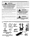
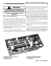
INSTALLATION INSTRUCTIONS
12
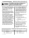
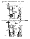
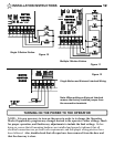
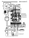
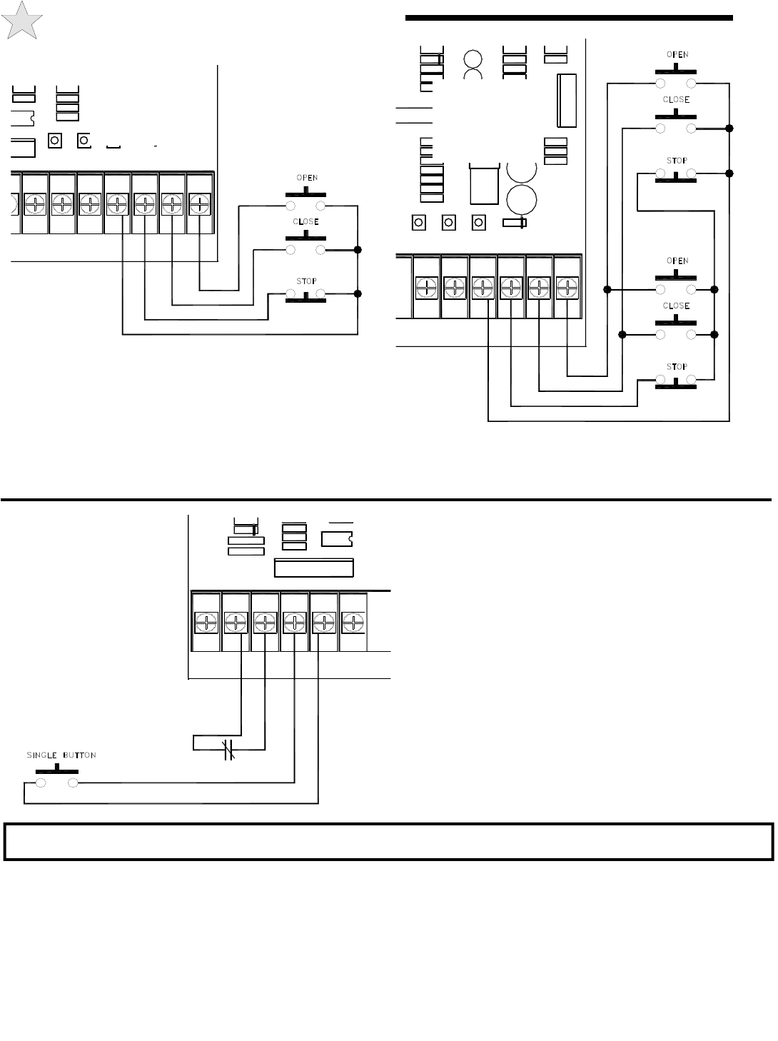
Figure 10
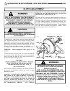
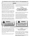
NOTE: It is now necessary to turn on the power in order to to change the Operating
Mode (if applicable), program any changes desired to the operator’s other settings, check
for proper operation, and finalize any adjustments to include the limit settings. Before
doing so, ensure that all mounting hardware are installed and properly tightened, that all
electrical connections are per local code requirements, and that proper wiring practices have
been followed. Also, double-check that all ropes have been removed from the door and
that the doorway is clear.
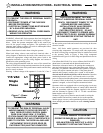
PCB 112695 REV B TSLK
OPEN
C25
PB1 PB2 PB3
U5
STOPCLOSEOPEN
C1
R84
R2
R3
D12
COM
CLOSE
STOP
NO REV
NC REV
PHOTO
RADIO
24V
R56
R55
R54
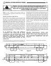
PCB 112695 REV B TSLK
OPEN
RM1
RM2
RM3
VCC
COM
P7
C25
R94
R87
R38
PB1 PB2 PB3
R5
R25
STOPCLOSEOPEN
C24
U1
D8
U4
C11
R30
R26
R29
C3
C1 C8
R95
R2
R3
D2
R65
C10
D3
C9
D12
R57
COM
CLOSE
STOP
NO REV
NC REV
MOTOR
CONTROL
BOARD
MOTOR
CONTROL
BOARD
Single 3 Button Station
Multiple 3 Button Station
Figure 11
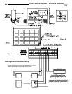
CDOMCB 2005
c.p. ALLSTAR COR
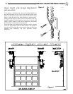
P
R8
R24
TB1
P5
R93
U5
R4
C21
D1
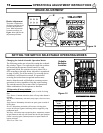
EXTERNAL INTERLOCK
PHOTO
COM
SINGLE
ILOCK
24 VAC
COM
MOTOR
CONTROL
BOARD
Single Button and External Interlock Wiring
Figure 12
Note: When adding an External Interlock
remove the factory installed jumper from
the connection terminals.
TURNING ON THE POWER TO THE OPERATOR