PTC Model III, Rotary Selector Installation Instructions and User Manual, Rev 8/03 - Page 3
Once you have selected your mounting location:
1. Mount the controller.
2. Connect the Motor to the Controller. Note that the motor
cable connector has two small tabs on one side; these tabs
should be facing up when you insert it into the Controller.
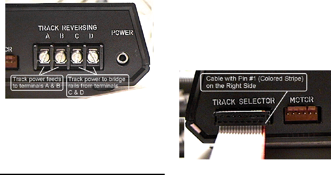
3. If you have ordered the optional Track Power Reversing
capability, connect the bridge track power leads to terminals
"A" and "B" on the rear of the Controller. Polarity is not
important. Connect the bridge track power feeders to
terminals "C" and "D" on the controller:
Figure 2: Controller (Rear View) and Bridge Connections
Note: Do not connect track power through the Controller if you
do not have the Track Reversing Feature installed. Power will
not be fed through.
After you have double checked the connections so far, continue
to installation of the Track Selector Modules.
TRACK SELECTOR INSTALLATION
Refer to Figure 3, "Track Selector Mounting Hole Pattern", to
familiarize yourself with the layout of the hole patterns and the
drills required.
Orientation of the Track Selector Module is not important. For
example, you can mount the rotary switch in the center of your
turntable layout schematic, and place the switch and LED holes
to the left or right, above or below the rotary switch.
After you have determined the desired location and orientation:
1) Drill the required hole pattern (the large hole and the three
medium sized holes).
2) Connect the flat ribbon Track Selector Cable to the Selector
Module. The cable should be connected to the J1 connector,
noted as "Primary" on the Selector Module PCB. The
marked edge of the cable must be oriented to line up with
the Pin 1 location of J1. Pin 1 is near the Head/Tail switch
(noted as "SW2" on the PCB).
3) Mount the Selector Module through the control panel:
A) Remove the rotary switch knob, red pushbutton cap,
LED bezel, and all switch hardware (nuts and washers)
except one nut on the toggle switch.
B) Install the LED bezel through the front of the control
panel.
C) Install the Track Selector through the control panel. The
rotary switch and the pushbutton switch should rest
flush against the back of the control panel. The LED
should protrude slightly through the LED bezel. Adjust
the nut on the toggle switch so the Track Selector is
level with respect to the rear of the control panel.
D) Install the lock washer and nut on the toggle switch.
Install the knurled nut on the pushbutton switch; discard
extra nut and lock washer if not needed. Install the lock
washer and nut on the rotary switch. Tighten all nuts.
Note: Tighten the rotary switch nut carefully, do not
overtighten.
E) Install the pushbutton cap.
4) Connect the Track Selector Cable to the Controller:
Important! Be sure the marked edge of the cable is on the
RIGHT as you view the rear of the controller. Installing
the Selector Cable in backwards may damage the
Selector Module. Be sure it is correctly installed before
turning the system power on.
5) After you have installed the Track Selector Module(s),
double check your connections. Be sure the main power
switch is on the down (off) position. Plug the Power Supply
cable into the Controller, and then plug the Power Supply
into the wall outlet. You are now ready to test and program
the Controller.


