3/13/2002 1000-223-00
FloScan Instrument Company, Inc.
Tel: (206) 524-6625 Fax: (206) 523-4961
3016 NE Blakeley Street, Seattle, WA 98105 email: service@floscan.com http://www.floscan.com
TROUBLESHOOTING
TwinScan
®
3” Instrument - Tachometer (LCD)
BEFORE CALLING FOR ASSISTANCE, COMPLETE THESE TROUBLESHOOTING CHECKS AND RECORD YOUR
FINDINGS. TECHNICAL SUPPORT REQUIRES THIS INFORMATION BEFORE A RETURN AUTHORIZATION WILL BE
ISSUED. IT TAKES ABOUT 20 MINUTES AND IS VERY IMPORTANT IN ANALYZING SYSTEM PROBLEMS.
Before starting, record instrument model number and switch settings.
MODEL # _____________________ SERIAL # ____________
RED SWITCH POSITION __________ BLACK SWITCH POSITION _________
Perform the Instrument Diagnostic Test First. Record your findings.
I. INSTRUMENT DIAGNOSTIC SELF-TEST
• Secure power to the Red, and Red/White wires, (Turn both key switches OFF).
• Turn power on, (Either to one or both switches). At start-up, the instrument automatically performs a, “Self-test”.
• Verify that the pointer’s back-lighting glows Red, and that the LCD back-light is glowing Green.
• Observe that the pointers smoothly sweep to near full scale, (Slightly above or below) then smoothly drop back to zero.
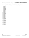
The LCD display shows the following numbers and letters in sequence. These are examples actual readings may vary. Switch settings
and configurations are shown on the LCD as, “0123456789AbCdEF”.
8.8.8.8 LCD segment and back-lighting check.
1.21 Software version number.
F 3 Red, (Port) and Black (Starboard) switch settings.
- - 34 Internal configuration (scale range, units, etc.)
Blank
≡ ≡ Synch display, (Indicates normal operation).
NOTE: If Tachometer is powered from on switch, a lower case oo will appear in one corner of the LCD.
• Record the software version __________ and switch settings _____ _____. FloScan Technical Support will ask for these.
The self-test verifies adequate power, a good ground, that the pointers move, and the LCD display is working.
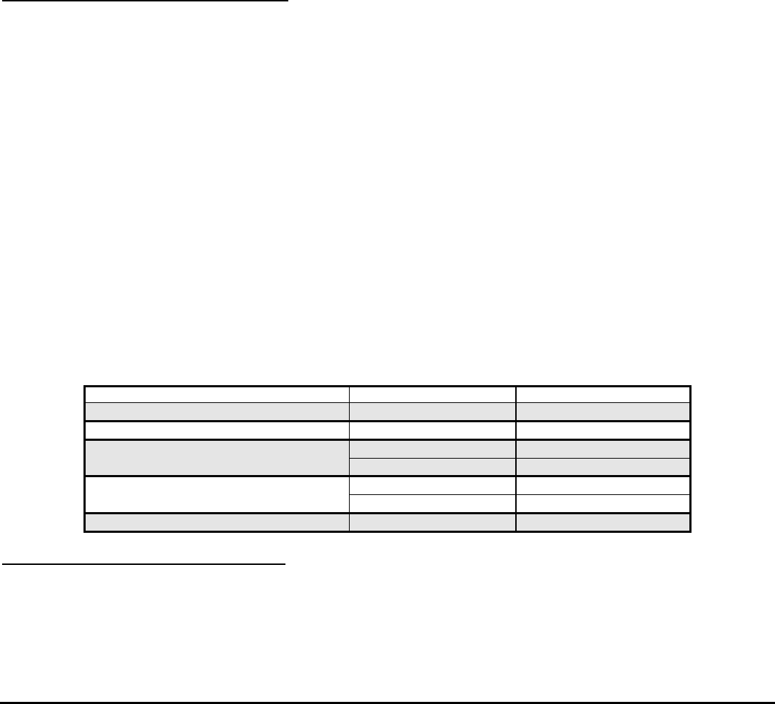
FAULT PROBABLE CAUSE SEE SECTION:
Blank LCD Display Wiring Section II
No back-lighting Wiring/bulb failure Section II
High, Low or No Tachometer Reading Wiring Installation sheet
Calibration Calibration sheet
Fluctuating Tachometer Wiring/continuity Sections II, III
In synch w/engine
Wire Harness Continuity Test Section III
II. SUPPLY VOLTAGE and GROUND TEST
• Measure voltage between the Starboard RED power wire, and the BLACK Instrument ground wire.
• Measure voltage between the Port RED/WHITE power wire, and the BLACK Instrument ground wire.
__________VDC
This reading should be approximately 12 VDC, but not lower than 10 VDC.