5/20/1999 1000-207-00
FloScan Instrument Company, Inc.
Tel: (206) 524-6625 Fax: (206) 523-4961
3016 NE Blakeley Street, Seattle, WA 98105 email: service@floscan.com http://www.floscan.com
CALIBRATION
TwinScan 3” Instrument – Tachometer (LCD)
Diesel Engines
The TwinScan 3” Tachometer is unique in that it can be calibrated for both gasoline and
diesel systems. On the back of the TwinScan 3” Tachometer Instrument, the RED
switch is used for fine calibration. The BLACK switch is used for coarse calibration.
You will use a combination of both switches for proper calibration.
DIESEL SYSTEM CALIBRATION
Diesel systems have three options for tachometer pick-up styles, Mechanical AC Generator, Magnetic Pick-up, and Alternator.
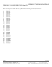
Table 1 will be used to calibrate any style of tachometer pickup you may have. Please read the section pertaining to your specific
tachometer pick-up style for instructions on calibrating the tachometer.
I. MECHANICAL AC GENERATOR
1. Determine the number of pole pairs of your generator. Some examples are:
Century Brass 8 Stewart Warner 8
Hewitt 8 Synchrostart 30
VDO 4 Motorola 8
2. Determine the ratio of the number of revolutions of the crankshaft drive to the number of revolutions of the tachometer. For
most engines, the ratio is 0.5. If you are not sure of your tachometer drive ratio, you can either check with your local engine
dealer or you can adjust the RED and BLACK switches until you get a reading of 500-800 RPM at a normal idle with the
engine at or near normal operating temperature.
3. Calculate the proper switch setting:
Tachometer drive ratio x number of generator pole pairs = number used to determine RED and BLACK switch settings
from Table 1.
Example: Installation - Caterpillar 3208 with an 8 pole pair generator.
Crankshaft revolution to tachometer drive = 0.5 ratio.
Generator = 8 pole pair.
0.5 (ratio) x 8 (pole pair) = 4 (generator produces 4 pulses per revolution).
The switch setting selection would be as follows:
50 RPM synchronized resolution - RED switch = 3 BLACK switch = 1
20 RPM synchronized resolution - RED switch = 3 BLACK switch = 9
II. MAGNETIC PICK-UP
This instrument must be calibrated at the time of installation to your specific engine in the following manner:
1. Determine the number of pulses of the magnetic pick-up per crankshaft revolution. If you are not sure what this is, contact
you local engine dealer and they can provide this information.
Pulses = (number of teeth on gear) x (number of revolutions of gear per crank shaft revolution).
The table steps allow setting to be within +/- 1% to 2% of the actual pulse count. As this applies to both engines, the
synchronizing accuracy is not affected.
2. Locate the number of pulses per crankshaft revolution in Table 1. Select the number closest to your actual pulses per
crankshaft revolution.
Example: Pulses per crank shaft revolution = 160. From Table 1:
50 RPM synchronized resolution - RED switch = B BLACK switch = 6
20 RPM synchronized resolution - RED switch = B BLACK switch = E
Back of Instrument
Dial Lamp
0 0
Wires
Calibration Knobs
Black Switch Red Switch