10/21/99 1000-109-00E
FloScan Instrument Company, Inc.
Tel: (206) 524-6625 Fax: (206) 523-4961
3016 NE Blakeley Street, Seattle, WA 98105 email: service@floscan.com http://www.floscan.com
WIRING
Installation Instructions
TwinScan
®
3” Instrument – Tachometer Only
Gas and Diesel Engines
To ensure years of trouble free operation of your new TwinScan
Instrument
please read all of these instructions carefully before beginning your installation.
CAUTION: To avoid electrical shorts and possible fire, turn OFF the power to the instrument panel until installation is complete.
WIRING
Use No. 18 AWG multi-strand wire, the included butt splices, and self-sealing heat shrink to make all connections. Alternate
installation: Use insulated ring tongue connectors and a terminal strip. DO NOT solder connections. Vibration can cause wire to
break where solder stops and cause intermittent connections.
Installation: Make a 3 3/8” diameter cutout in the instrument panel for the instrument.
Important: Protect wires from damage caused by sharp edges, moving and hot engine parts. Cable tie and support all wire runs for
safety.
MAIN WIRING
Wire Color Function
RED/WHITE PORT + 12 VDC Power
RED STARBOARD + 12 VDC Power
BLACK Battery Ground
YELLOW PORT tachometer input
VIOLET STARBOARD tachometer input
BLUE Flow Input
WHITE/ORANGE GPS Input, NEMA + (A)
GREEN/BLACK GPS Input, NEMA - (B)
1. Connect the RED/WHITE stripe wire to the “power on” side of the
PORT engine key switch.
2. Connect the RED wire to the “power on” side of the STARBOARD engine key switch.
3. Connect the BLACK wire to the negative (-) side of the battery buss.
4. Connect the YELLOW wire to the PORT engine tachometer pickup.
5. Connect the VIOLET wire to the STARBOARD engine tachometer pickup.
Note: If not installing a TwinScan GPH instrument, leave the following wires disconnected (tape them off).
6. Connect the BLUE wire to the WHITE/RED wire from the TwinScan GPH instrument.
7. Connect the WHITE/ORANGE wire to the GPS (+) terminal (A).
8. Connect the GREEN/BLACK wire to the GPS (-) terminal (B).
NOTE: The industry standard for tachometer pickup wire(s) color coding is as follows:
PORT side = GREY/RED STARBOARD side = GREY/GREEN
This completes the Tachometer wiring. See TACHOMETER CALIBRATION sheet for calibration information.
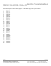
Back of Instrument
Dial Lamp
0 0
Wires
Calibration Knobs
Black Switch Red Switch