38-8
Cisco IE 2000 Switch Software Configuration Guide
OL-25866-01
Chapter 38 Configuring Standard QoS
Information About Standard QoS
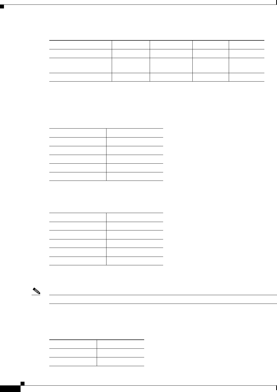
Table 38-5 shows the default CoS output queue threshold map when QoS is enabled.
Table 38-6 shows the default DSCP output queue threshold map when QoS is enabled.
Default Mapping Table Settings
Note If these values are not appropriate for your network, you need to modify them.
Table 38-7 shows the DSCP-to-CoS map to generate a CoS value, which is used to select one of the four
egress queues.
Maximum threshold 400 percent 400 percent 400 percent 400 percent
SRR shaped weights
(absolute)
1
25 0 0 0
SRR shared weights
2
25 25 25 25
1. A shaped weight of zero means that this queue is operating in shared mode.
2. One quarter of the bandwidth is allocated to each queue.
Table 38-4 Default Egress Queue Settings (continued)
Feature Queue 1 Queue 2 Queue 3 Queue 4
Table 38-5 Default CoS Output Queue Threshold Map
CoS Value Queue ID–Threshold ID
0, 1 2–1
2, 3 3–1
4 4–1
5 1–1
6, 7 4–1
Table 38-6 Default DSCP Output Queue Threshold Map
DSCP Value Queue ID–Threshold ID
0–15 2–1
16–31 3–1
32–39 4–1
40–47 1–1
48–63 4–1
Table 38-7 Default DSCP-to-CoS Map
DSCP Value CoS Value
0–7 0
8–15 1


