Component Replacement: Flow Meter – Body
InfraStruXure InRow RC Service 45
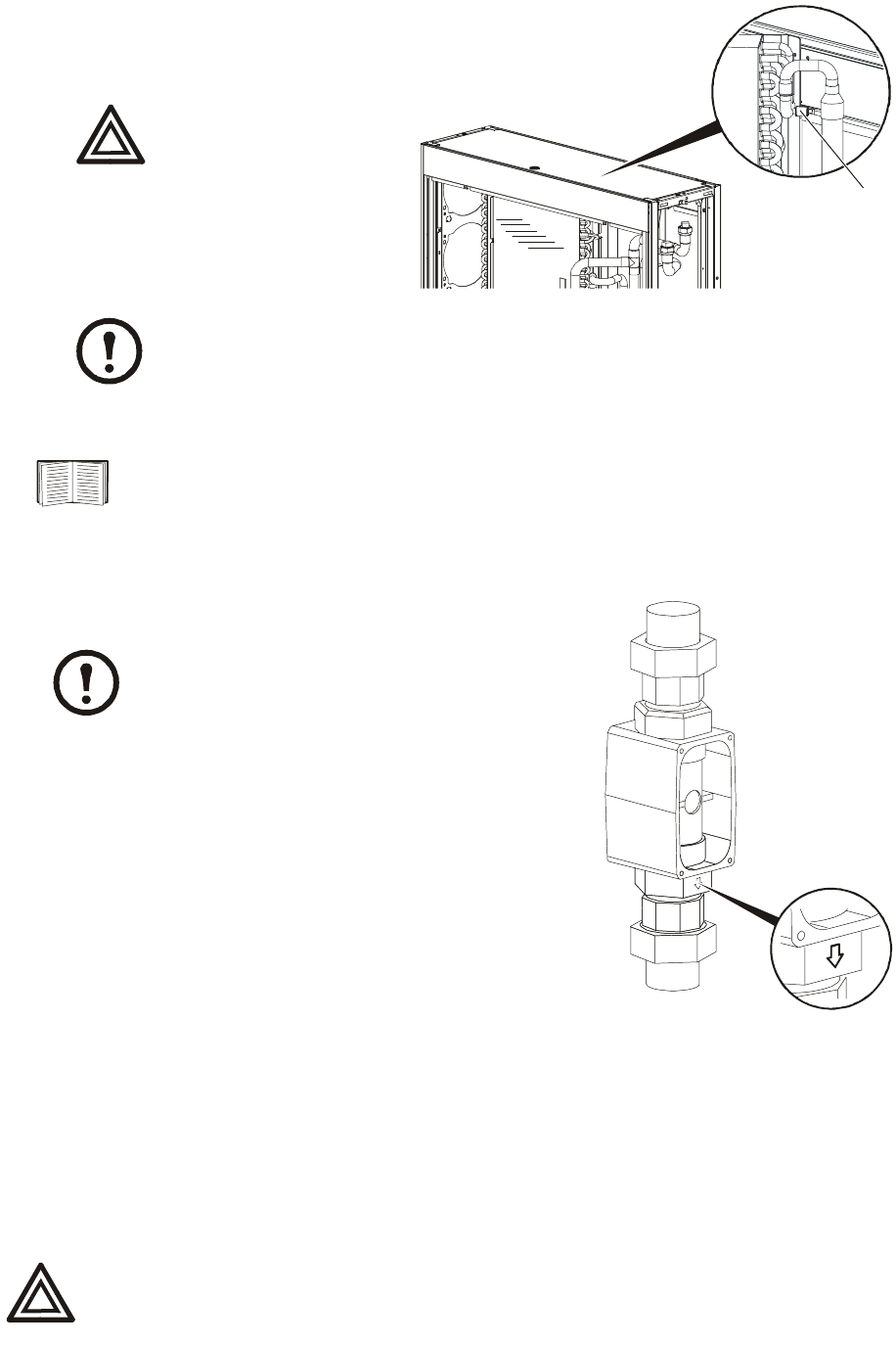
f. Open slightly the pipe vent schraeder
valve at the top of the unit just before
the top coil to allow the remaining
coolant in the piping to drain.
g. Close the hose bib once the unit is
drained.
8. Remove the flow meter electronics module.
9. Remove the flow meter from the unit piping by disconnecting the pipe unions directly above and
below the meter.
10. Install the new flow meter body into the existing pipe unions
and tighten the fittings.
11. Use an allen-wrench to rotate the 3-way valve actuator to
the full cool position.
12. Open slightly the top vent on the bottom coil.
13. To pressurize the piping, slowly open the return water valve
at the CDU or in the external piping, depending on your
configuration.
14. Air will begin to bleed from the coil vents. Close the bottom
coil vent plug when you see a small stream of water.
Continue to bleed the air from the top coil vent plug until
you see a small stream of water there as well, then tighten
and close the vent.
15. Once the air is bled from the system and the vents are closed tightly, open the water supply to the
unit (either at the CDU or in your external piping), return the 3-way valve to full-bypass, and open
the internal bypass and supply valves.
16. Check the flow meter piping for leaks, replace any pipe insulation removed earlier, replace filters
and doors, and return the unit to service. Verify that the flow meter is operating properly.
Warning
Failure to open the hose
bib before the coil vent
will release pressurized
coolant out of the vent in
the interior of the unit.
Note
Glycol must be disposed of properly.
See “Flow Meter – Electronics Module” on page 43 for instructions.
Note
The flow meter body must be installed with the
arrow pointing down.
Warning
Doors and panels are equipped with locks. Locks must be engaged while the
unit is operating.
na1768a
Top Coil
Vent
na2054a


