


4
INSTALLATION
1. Turn o electrical power to the system at the
fuse box or circuit breaker. Also turn o the
main gas supply.
2. If replacing an existing valve, disconnect all
plumbing and electrical connections from the
old control.
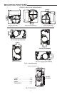
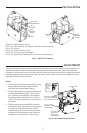
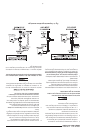
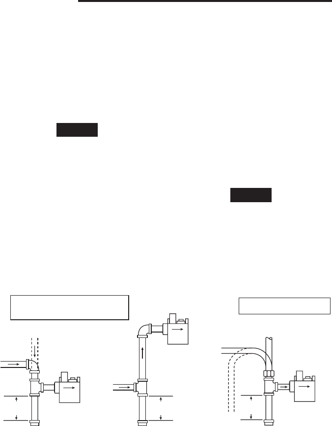
3. The control may be installed upright, + or
– 90˚ from upright, or vertical (refer to g. 2).
The arrow on the valve indicates the direction
of inlet gas ow.
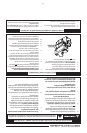
Piped Gas
Supply
Piped Gas
Supply
Tubing Gas
Supply
NOTE: ALWAYS INCLUDE A
DRIP LEG IN PIPING
Figure 2. Typical gas valve piping
NOTE: A MANUAL SHUTOFF VALVE
MUST BE INSTALLED WITHIN
6 FEET OF THE EQUIPMENT
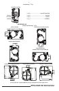
Horizontal
Drop
3 in.
minimum
Gas Valve
Gas Valve
Riser
3 in.
minimum
Drop
Horizontal
Riser
Gas Valve
3 in.
minimum
NOTE
All piping must comply with local codes,
ordinances, and/or national fuel gas codes.
4. You should use new pipe that is properly
chamfered, reamed, and free of burrs and
chips. If you are using old pipe, be sure it is
clean and free of rust, scale, burrs, chips, and
old pipe joint compound.
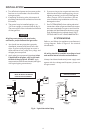
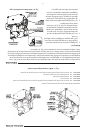
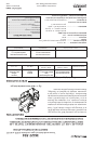
5. Apply pipe joint compound (pipe dope) that
is approved for all gases, only to the male
threads of the pipe joints. DO NOT apply
compound to the rst two threads (see gure
4 for typical piping connections).
6. If you are using a vise or open-end wrench to
hold the valve while installing piping, do not
tighten excessively, as this may damage the
valve. (Torque: 375 in-lb maximum.) Do not
cross-thread during installation as this may
damage the valve.
7. See SYSTEM WIRING when making electrical
connections. After all gas and electrical connec-
tions are completed, turn gas on and check for
gas leaks with leak detection solution or soap
suds. Bubbles forming indicate a leak. SHUT
OFF GAS AND FIX ALL LEAKS IMMEDIATELY.
SYSTEM WIRING
Refer to and follow the appliance manufacturer's
wiring diagram. Refer to figure 5 for terminal
identication.
NOTE
All wiring should be installed according to local
and national electrical codes and ordinances.
Always check that the electrical power supply used
agrees with the voltage and frequency shown on
the gas control.
Fig. 4 – Typical Gas Valve Piping