


5
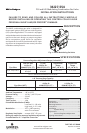
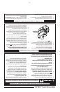
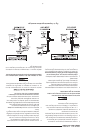
The gas valve outlet pressure was pre-adjusted for both Nat. and LP at the factory, but ne adjustment
is possible by removing the access plug and turning the ne-adjustment screw with a 1/8" at blade
screwdriver. Adjustment must only be done while monitoring outlet pressure with a suitable manometer
properly attached to the outlet pressure tap. The outlet pressure tap must be leak checked after reseal-
ing (refer to Notes and Fig. 6 below).
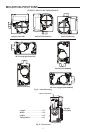
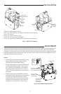
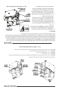
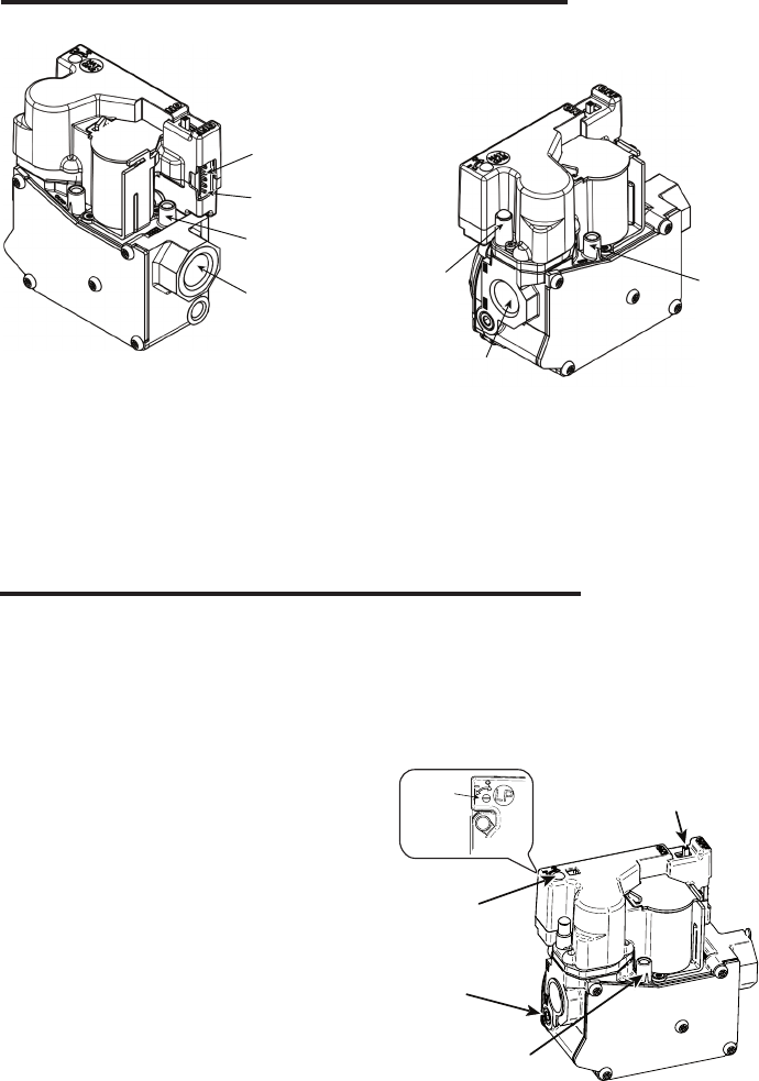
Fig. 6 – 36J27 Modulating Gas Valve
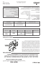
Fig. 5 – 36J27 Valve Features
OUTLET
PRESSURE
TAP POST
VALVE OUTLET
RE
GULATOR
VENT
ELECTRICAL
5 PIN CONNECTOR
PIN 1
LOCATION
INLET
PRESSURE
TAP POST
VALVE INLET
Electrical 5 PIN Connector Pin Out
PIN 5 - TH - Main Valve 24 VAC (top pin, with the cover pointing up)
PIN 4 - TR - Ground
PIN 3 - TX - Communication to IFC
PIN 2 - RX - Communication to Stepper
PIN 1 - TH - Board 24VAC (bottom pin, with the cover pointing up)
Notes:
1. The maximum outlet pressure adjustment using
the ne adjustment screw is approximately
±15% from the original factory setting.
2. The ne adjustment screw has 16 detents and
can be rotated innitely 360° in either direc-
tion. However, at some point in the rotation,
the outlet pressure will switch from +15% to
-15% or vice versa, depending on the direction
of rotation.
3. The ne adjustment screw aects the entire
modulation range. Therefore, once adjustment
is made, the valve outlet pressure must be
checked at both the minimum and maximum
extremes of the modulation range. (Refer to
the appliance manufacturer’s instructions.)
.093 SOCKET HEAD
SCREW OUTLET
PRESSURE TAP
(SOME MODELS)
1/8 - NPT OUTLET
PRESSURE TAP
(SOME MODELS)
ON/OFF SWITCH
ACCESS PLUG - (PRESSURE
FINE ADJUSTMENT SCREW
IS LOCATED BENEATH PLUG)
TURN SCREW
TO INCREASE /
DECREASE
OUTLET
PRESSURE
INSTALLATION
ADJUSTMENT