


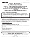
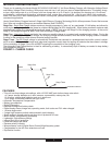

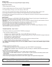

FIGURE 3A (FRONT VIEW)
WARNINGS: THERE ARE NO USER-SERVICEABLE PARTS IN THIS CHARGER. DO NOT OPEN THE UNIT! IT MUST
BE RETURNED TO POWER ON BOARD FOR PROFESSIONAL TESTING AND REPAIR. OPENING THE
UNIT WILL VOID THE MANUFACTURER'S WARRANTY.
Contact the Vector Technical Support Department at (954) 584-4446 or toll free: (866) 584-5504 for further information.
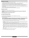
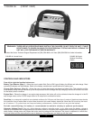
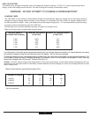
CONTROLS AND INDICATORS
From left to right the function buttons are:
Battery Type Selector (Step 1)
- Allows the user to select Wet, Gel or AGM type of battery for efficient and safe charge. Most
automotive batteries are Wet batteries. Refer to the battery manufacturer’s specifications for battery type.
Charge Rate Selector (Step 2) - Allows the user to select the charger rate based on battery size. This selection and the
actual battery charge rate are monitored by the microprocessor and the charger will stop charging if the rate is too fast or too slow
for the battery size or condition.
Engine Start - Places the charger in an engine start sequence, this button will not be activated unless the charger is in the 25
amp charge mode, set the 2/10/25 amps button to 25 amps first to activate this button.
Desulfate- Is an automatic mode that once started continues for 24 hours and then stops. A series of electrical pulses breaks
the crystalline form of lead sulfate to return these chemicals into useful battery electrolyte. More than 24 hours may be need-
ed to restore. If 5 cycles does not improve battery performance, discontinue and re-cycle the battery.
Periodic reconditioning of a battery is recommended to maintain a battery’s optimum performance
Alternator Voltage Check- Can only check alternator voltage in standby mode. In any other mode the battery voltage is
checked to check alternator voltage press and hold down button for 5 seconds and release and the voltage will be displayed.To
check battery voltage press and release the button and the voltage will be displayed This check is repeated at various elec-
trical load levels and the tests allow the user to determine if the alternator can keep up with the loads.
FIGURE 4A: Control Panel
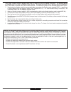
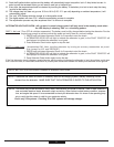
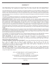
FIGURE 4B: Digital
Readout Circulating
Pattern
6