


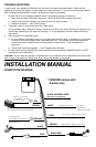
FILE: DTP\MANUAL\VS235255XRInstMenuVer1b.P65\MAY2000 ORDER PART# 760-899-2\909
GREY AND BROWN WIRES — To automatic door lock/unlock (VS255XR only)
The power door lock outputs may be connected to a car which has existing or add-on power door lock switching
relays. The transistor ground output is high enough to energize most switching relays.
When disarmed, UNLOCKS the doors with a 0.5 second ground output. When armed, LOCKS the doors with a 0.5
second ground output.
DO NOT CONNECT THESE POWER DOOR LOCK WIRES DIRECTLY TO THE DOOR LOCK ACTUATORS, AS
THIS WILL DEFINITELY BURN OUT THE ALARM SYSTEM.
Installation will vary from car to car, depending on the car's power door lock wiring. In most cases, a separate door
lock interface module SEA169 is required. Mercedes and Audi owners will need a different model (SEA168).
Please refer to the module's manual for more information.
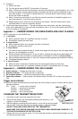
ADJUSTING THE SHOCK SENSOR
1. Remove the back cover.
2. Use a small, flat-blade screwdriver to turn the adjustment knob.
3. When turned clockwise, the sensitivity is increased. If turned counterclockwise, the sensitivity is decreased. Do
not overturn the potentiometer, as it may break, only 270 degree adjustment range.
4. To test the sensitivity, kick a wheel lightly, and siren will "chirp," then kick hard enough to trigger the alarm at
the desired point. If it does not "chirp," the sensitivity should be increased. If the wheel is lightly kicked and the
alarm sounds, the sensitivity should be decreased. Check all wheels for consistency.
Note — To prevent false alarms, the shock sensor will not trigger the alarm until 4 seconds after the alarm is armed
and no further motion is detected.
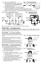
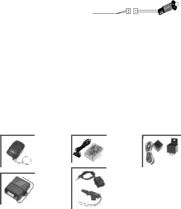
PLUG-IN LED 2-pin RED connector Fig. 7
A. Determine where to mount the LED. The LED should be
easily seen by potential thieves and vandals. However, do
NOT mount where the LED is easily exposed to
sunlight. Discuss the LED location with the customer before starting.
B. Drill a 6 mm hole in the LED location.
C. Run the LED connector through the hole, and then plug into the alarm brain’s 2-pin RED connector.
IMPORTANT The LED operates on +5V, not +12V. DO NOT CONNECT THE LED
DIRECTLY TO THE CARS BATTERY, OR IT WILL BURN OUT.
SPECIFICATIONS
POWER: 12VDC. Negative ground ALARM DURATION: Automatically resets after one cycle of 30 seconds
TRIGGER INPUTS:
Current sensing, shock sensor, ignition sensing, and door switch
ALARM OUTPUTS:
Alarm status arming LED, engine immobilizer, flashing lights (10A relay output, VS255XR
only), door lock/unlock (0.3A transistor ground output, VS255XR only)
ARM/DISARM INDICATOR:
1 chirp signals arm, 2 chirps signals disarm
TRANSMITTER/RECEIVER:
Modulation — AM; Antenna impedance — 50 ohms; RF carrier frequency —
304MHz; Digital Rolling Code — 1.8 x 10
19
possible codes, up to 4 transmitters can be learned.
ACCESSORIES INCLUDED:
a. 2 RF transmitters with battery b. Siren/alarm brain and built-in shock sensor in one module
c. Operation/Installation manual d. Mounting hardware
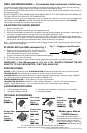
OPTIONAL ACCESSORIES:
Fig. 7 — Plugging in the LED switch
LED
SEA110
3 Button
Remote
(SEA933)
Dual-stage
glass-break
sensor
(SEA857)
Make your alarm
YOUR alarm!
Your dealer has a wide variety of
accessories which can increase your
alarm's security and convenience.
Ask for more information. And insist
on GENUINE UNIDEN accessories!
Garage Door
and House
Alarm
Interface
(SEA910)
Central Lock
Interface
(SEA169)
and
Door Lock
Motor
(SEA170)
Engine
Immobiliser
Relay &
Socket set
(SEA865)
The Uniden policy is one of continual development and improvement.
For that reason, Uniden reserves the right to change specifications without notice.