


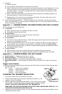
B. Connect the fused ORANGE WIRE:
(1) Single-wire parking light systems — Most vehicles
have a single circuit which controls all parking lights. In
this case, connect the fused ORANGE WIRE to the
(+) parking light wire. See fig. 2.
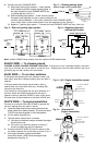
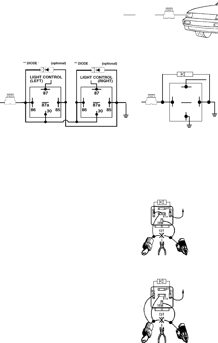
(2) Dual-wire parking light systems — A few vehicles (mainly
European) have separate circuits for parking lights for the
vehicle's right and left sides. In this case, connect the fused ORANGE WIRE
to two relays, each of which feeds power to the two separate circuits. See fig.3.
(3) Negative (-) parking light system — Connect the fused ORANGE WIRE to a relay. See fig.4.
Note: Uniden SEA865 relays already have the optional SP898 diodes fitted.
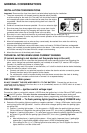
BLACK WIRE — To chassis ground
CHOOSE A GOOD CHASSIS GROUND LOCATION. If the ground is not connected properly, the alarm
may act as if armed, but not be able to sound the siren. Scrape paint from the metal surface, and use a
grounding lug and star washers for best results.
BLUE WIRE — To car door switches
If the vehicle has existing car door switches, locate a car
door switch wire which changes polarity when any door is
opened:
If the door switch wire shows ground when a door is
opened (this is the case with most cars, including GM),
connect to the blue wire.
If the vehicle is not equipped with car door switches, or if
the door switch wire shows positive when the door is
opened, install pin switches SEA876 in each of the doors.
Connect each of these switches to the alarm's BLUE wire.
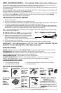
WHITE WIRE — To engine immobilizer
Connect to an optional 30A relay SEA865 to prevent the
car from starting when the alarm is armed.
A. Locate the starter solenoid wire (carries power from the
ignition switch to the starter solenoid). This wire must show
+12VDC only when the ignition is in the start position.
B. Cut the starter solenoid wire.
C. Test the starter solenoid wire as follows:
(1) If the wire is cut before the engine is started, the engine
should not turn over.
(2) If the wire is cut while the engine is running, it
should not affect the engine’s operation.
D. Connect the WHITE WIRE and the two halves of the
cut starter solenoid wire to the relay as shown in fig. 5.
E. If the engine still starts, connect terminal 86 to
a wire which shows +12VDC when the engine is both
starting and running (fig. 6).
Fig. 4— Negative single-wire
parking light system
Fig. 3— Dual-wire parking light systems
10A
To ORANGE
WIRE
Fig. 2 — Flashing parking lights
Ø ORANGE
Positive single-circuit parking lights
10A
Fig. 5— N.C. Engine Immobilizer output
Fig. 6— Alternate N.C.
Engine Immobilizer
Ignition
switch
Starter
solenoid
To alarm WHITE
engine
immobilizer
output wire
Starter
solenoid
Ignition
switch
To alarm WHITE
engine
immobilizer
output wire
SEA865
SEA865
SEA865
SEA865
SP898
SP898
30
87
87a
86 85
10A
To ORANGE
WIRE
SEA865
** DIODE SP898 (optional)
SP898
SP898