


IMPORTANT
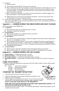
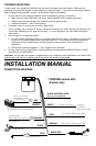
Fig. 1
GENERAL CONSIDERATIONS
INSTALLATION CONSIDERATIONS
Important: Disconnect the fuse from alarm's red wire before beginning the installation.
1. The alarm comes with a U-shaped mounting bracket which provides
a solid mounting for the main unit. The main unit should be located in
an inconspicuous place under the hood as far away from the engine
as possible. Mount the siren trumpet pointing down so it does not
collect water.
2. Solder all connections whenever possible. Do not run wires too tight.
3. Run wires away from sharp edges which may cause short circuits.
Protect wires with tubing or by wrapping with electrical tape. Use
grommets when wires are run through holes in the car body.
4. Run wires in such a way that the alarm is positioned higher than the wires (see Fig.1).
5. Mount all components in such a way that the normal operation of the vehicle’s moving parts is not
impaired or interfered with.
6. Mount all components and run wires so they cannot easily be reached from under the vehicle by
someone attempting to defeat the system.
7. With the alarm disarmed, remove the battery cover and insert a 9V Nickel-Cadmium rechargeable
battery (not included) to provide backup power to the alarm. If the main power cord is cut, the alarm
will function normally for at least 24 hours, except current sensing.
8. Mount the siren out of the direct path of water.
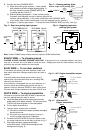
TECHNICAL NOTES WHEN USING CURRENT SENSING
(If current sensing is not desired, cut the purple loop in the unit)
1. If the vehicle has a built-in noise filter that prevents the current sensing function from triggering the
alarm, use a charged non-polarized capacitor (not included) of at least 47µF rated at 16V or higher.
Connect it in parallel to the dome or courtesy light.
2. False alarms may result if the alarm is over-sensitive, or if a built-in electrical device drains the battery
when the vehicle is parked. In this case:
a. Connect one lead of a non-polarized capacitor to where the alarm's red wire connects to power.
Connect the other lead of the capacitor to the chassis.
b. For vehicles with a built-in impulse winding clock that draws current when the clock is winding,
replace it with a constant-current clock or connect it to a separate battery.
RED WIRE — Main power
DO NOT CONNECT THE RED WIRE DIRECTLY TO THE BATTERY. Connect the red wire to an
unswitched positive terminal of the fuse box, or to an (unswitched) source of +12VDC which is at least 1
meter away from the battery.
YELLOW WIRE — Ignition switch voltage input
Connect to a fuse or a wire which outputs +12VDC when the ignition key is in the ON and START position,
but not the ACC position. This wire must be connected at all times to ensure proper arming and
disarming, as well as to operate the valet, emergency disarm, programming, and code learning process.
ORANGE WIRES — To flash parking lights (positive output) VS255XR only
A. Determine if the parking lights are positive or negative switched — Using a VOM meter, test the wires
coming from behind the light switch. Look for a wire which changes polarity when the parking lights
are turned ON:
(1) Positive (+) parking light system — If a wire goes to +12VDC when the parking lights are turned
ON, but shows no voltage with the parking lights turned OFF, this is the (+) parking light wire.
(2) Negative (-) parking light system — If a wire goes to ground when the parking lights are turned ON,
but shows no ground with the parking lights turned OFF, this is the (-) parking light wire.
(3) NOTE:
a. Most vehicles have (+) parking light systems. A few (mainly Japanese) have (-) parking light
systems (the (-) signal usually triggers a relay to send +12VDC to the parking lights).
b. If the voltage on the (+) or (-) parking light wire varies when you dim or brighten the interior
lights, then this is not the correct wire.