


24
7. 5 EXT TRIG (External trigger)
Charge begins to accumulate after the trigger input, and 1 frame images are output. There are five modes: 1P
SNR, 1P SR, PW SNR, PW SR, RR.
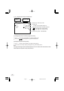
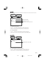
The RGB terminal trigger input and index output interface are as shown below.
5V
15kΩ
1SS357
150Ω
Trigger input
(CMOS out)
INDEX out
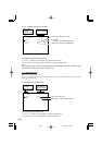
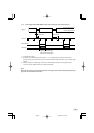
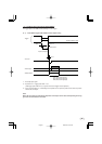
( 1 ) 1P SNR (1 Pulse Trigger Sync Non Reset)
Charge begins to accumulate after the trigger input to the RGB terminal, and 1 frame images are output.
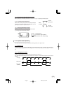
(1. 1) 1 Pulse Trigger SYNC-NON RESET Picture Output Timing
(At Time of One-shot or Continuous External VD/Continuous External HD Input)
*1: Externally input signal
*2: Exposure time is determined by the setting of "7. 2 (1.3) Changing each setting in E.TRG mode".
*3: Video is output at the falling edge of the internal VD following completion of the exposure period.
The video and the VIDEO INDEX have a paired relationship.
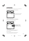
Note:
When the next trigger is input before completion of the output of the video corresponding to the trig-
ger, there will be an effect on the video.
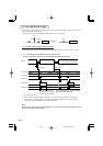
About 1 µs
Video output
796H (Partial scanning OFF)
387H (Partial scanning 60fps)
258H (Partial scanning 90fps)
The internal VD falling edge is within the exposure
period and thus video is not output.
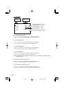
*
3
VIDEO INDEX
External VD IN*
1
External HD IN*
1
(Internal VD)
Trigger*
1
About 1H
Negative polarity mode
Positive polarity mode
Exposure period*
2
Exposure period*
2
2004.04.05, 8:51 AMPage 24