


12
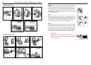
Installation of the hands-free car kit
13
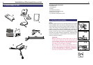
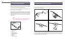
The two ‘Phone-In’ cables are marked accordingly and must be plugged into the appropriate con-
nections on the radio (blue, green or yellow). In this regard, please refer to the instructions
concerning the connection configuration of your car radio in your car radio handbook. In lots of
radios, the volume level (feedback of your conversation partner) can be controlled via the phone
input and the selection of the loudspeaker.
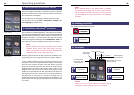
Different connections of the ISO plug on the radio
The layout of the pins on the ISO plug used in a car depends on the type of car. Before using the
switchbox, you should make sure that the connections are correct in order to prevent possible
damage to the device.
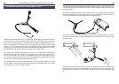
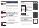
Configuration I
If the assignment of pin 7 of the ISO plug is connected to the DC Power Supply, and pin 4 is
connected to the ignition, you should check if the connection looks like the connection presented
on the drawing below.
Switchbox Vehicle
red 7 (red)
blue 4 (blue)
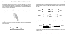
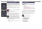
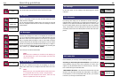
Configuration II
If the assignment of pin 7 of the ISO plug is connected to the ignition, and pin 4 is connected to the
DC power supply, the connection of the cables should look like the connection presented on the dra-
wing below.
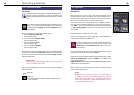
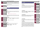
In the operating manual of the radio device, you can find the pin assignment for the “mute” signal. This
signal can occur on one of three cables marked with “mute1”, “mute2”, or “mute3”.
Connect the yellow “mute” cable to the switchbox using the correct cable from the car radio: “mute 1”,
“mute 2” or “mute3”.
ATTENTION:
The positive wires and ignition wires are protected in the casing of the switchbox with
3A fuses.
red 7 (red)
blue 4 (blue)
Switchbox
red 7 (red)
blue 4 (blue)
Switchbox
Vehicle
Vehicle
mute 1
radio device Switchbox
mute 2
mute 3
mute (yellow)