


172-082010_400 I Series Software Page 9 of 35
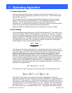
The network setpoint may be set via v4 or v5. v4 generates a setpoint in units of flow and v5
generates a setpoint in % of full scale. Either value may be read or written. Writing to one will
cause the embedded processor to calculate the value of the other and update it also.
The active setpoint values v6 & v7 or v4 & v5 become the source for the implemented setpoint
values v8 & v9.
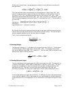
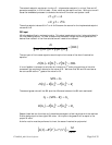
PID input
V8 is the desired flow in engineering units. This value is equivalent to the f value calculated in
the Flow Reading section. In order to determine the sensor voltage that would generate this
desired flow value all of the flow calculations will need to be reversed.
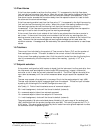
The next part of the inverse equation would require the inverse of the shunt linearization
equation.
It is not feasible to attempt to calculate an inverse to a 4
th
order polynomial so an iterative
process will be required to determine the value of SL. We know that SHL and SL are close so
we can use SHL as the 1
st
guess of the value for SL.
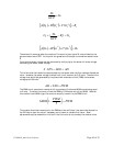
The second guess value will be SHL plus the difference between the SHL and resultant#1
Repeat these last two functions until the series converges in a few iterations with the resultant
R value being equal to the original SHL value. At this point the guess G will be equal to the
proper SL value.
A similar routine must be performed to invert the sensor linearization polynomial.
%52/4
425
vgv
vgv
=
=
⋅
()()()()()
[]
()
SHL
TcSpFVcFTcFShF
v
=
8
()
[
]
[
]
1
4
1
2
11
RGFGEGD =++
()
[
]
[
]
SHLSLFSLESLD =++
42
211
)( GRSHLG
=
−
+
1
GSHL
=
()
[
]
[
]
2
4
2
2
22
RGFGEGD =++
()
(
)
[]
GCF
SL
SCSBSA =
′
+
′
+ )(
53