


141-072011 - 201/203 Series Page 21 of 23
D) This formula provides approximate results that tend to be undersized because it neglects
pressure drops internal to the flow controller, compressible gas effects and temperature effects.
Multiply the result by ≈1.5 to get the expected minimum orifice size that can reliably pass the
desired flows at the expected pressures.
Where:
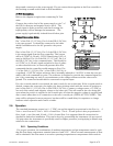
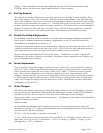
Formula 1: Formula 2:
D
= Orifice Diameter
Q
= Flow rate in standard volumetric unit (slm, sccm, scfh)
P
0
= Standard Pressure (760 Torr, 101.325 kpa)
P
u
= Upstream pressure in absolute units (use minimum expected value)
P
d
= Downstream pressure in absolute units (use maximum expected value)
γ
= Ratio of specific heats, ≈ 1.2 for monatomic gases, 1.4 otherwise
ρ
0
= Density of gas @ standard pressure and temperature of flow unit
π
= Pi (3.1415…)
σ
= Specific gravity of gas (ratio of gas density to density of air)
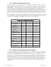
Choose the available orifice with the closest diameter that is larger than the calculated diameter.
Orifice diameters (inches) available are 0.023, 0.032, 0.046, 0.086, 0.130, 0.156, 0.250, 0.312,
0.375, 0.500 (large base only). Contact factory to order new orifice.
As an example, if the maximum controlled flow will be 1000 slm of air with an upstream pressure of
50 psig and exhausting to atmospheric pressure the minimum orifice diameter calculated from the
previous equation would be 0.225 inches. The next larger orifice that has a diameter of 0.250 inches
should be installed.
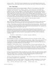
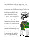
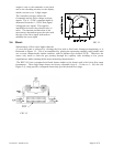
4.7.1. HFC-203 Orifice
To change the orifice in the HFC-203 unit, the valve must be dismantled. Remove the four 1/4"
Allen head machine screws in the top of the main valve. Lift off the valve top, exposing the spring
and diaphragm. Note that a small brazed ball bearing
is on the down stream side of the valve top. Remove
the spring and diaphragm assembly. The orifice is
located in the bottom of the valve body and can be
removed with a 9/16 socket wrench. See Figure 4.5.
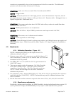
To reinstall an orifice, first install the gasket onto the
orifice (replacement gaskets can be obtained from the
factory). Next screw the orifice into the valve base.
Snug up the orifice but do not over tighten. Place
diaphragm assembly into the base. Line up the two
small holes in the diaphragm with the two small holes
in the valve base. Place the spring on top of the
()
4
2
00
2
8
π
ρ
σ
P
PPP
Q
D
dud
−
=
4
2
00
2
2
16
π
ρ
γ
σ
P
P
Q
D
u
=