


141-072011 - 201/203 Series Page 10 of 23
the ground connection at the power supply. Do not connect them together at the flow controller as
the resulting crosstalk could result in flow instabilities.
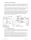
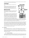
24 Volt Connections
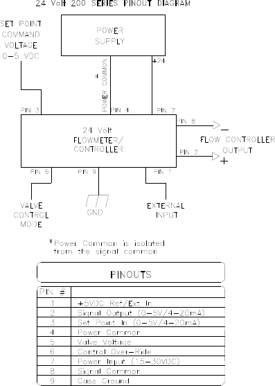
Refer to the diagram at right when connecting 24 Volt
units.
Connect the positive lead of the power supply to pin 7 of
the DE-9 connector and negative lead to pin 4. The
supply input is diode protected such that reversing the
input polarity will not damage the instrument. The
power supply is galvanically isolated from all other pins.
General Connection Notes
Pin 7 of the DA-15 (15 Volt), Pin 9 of the DE-9 (24 Volt)
is the case ground. It should be connected to the cable
shield if available and to the AC ground to the power
supply.
Pin 6 of the DA-15 (15 Volt), Pin 2 of the DE-9 (24 Volt)
is the output signal from the flow controller. This output
will be 0-5VDC/(4-20 mA), 5VDC/20mA being 100% of
rated or full flow. Pin 14 of the DA-15 (15 Volt), Pin 3 of
the DE-9 (24 Volt) is the command input. This should be
a 0-5VDC or (4-20 mA) signal and must be free of spikes
or other electrical noise, as these will generate false flow
commands that the controller would attempt to flow. Pin
15 of the DA-15 (15 Volt), Pin 1 of the DE-9 (24 Volt) is
a regulated +5.00VDC output reference that is normally adjusted to 5.01VDC so that the user can
achieve full scale command set point. The reference is designed to provide the command signal for
pin 14 by connecting one end of a potentiometer to the voltage reference and the other end to
ground. The center lead would then be connected to setpoint input.
If a valve override switch is not desired, the unit is ready for use at this time. If the override switch is
desired, connect the center pin of a single pole, three-position switch with the center off position to
pin 8 of the DA-15 (15 Volt), Pin 6 of the DE-9 (24 Volt). Connect a voltage source >10 VDC to
one end of the switch, and negative voltage to the other end. This will result in the valve being full
open when the positive is supplied to the override pin, off when the negative voltage is supplied and
auto-control when there is no connection to the valve override pin (OPEN-AUTO-CLOSE). This
setup will be adequate for most purposes, but there will be a small delay for capacitors to charge
between switch operation and control override.
2.6. Operation
The standard instrument output is a 0 - 5 VDC out and the signal is proportional to the flow i.e., 0
Volts = zero flow and 5 Volts = 100% of rated flow. The 4 - 20 mA option is also proportional to
flow, 4 mA = zero flow and 20 mA = 100% of rated flow. It is suggested that all connections be
checked for leaks after installation. This can be done by pressurizing the instrument (do not exceed
500 psig unless the instrument is specifically rated for higher pressures) and applying a diluted soap
solution to the connections.
2.6.1. Operating Conditions
For proper operation, the combination of ambient temperature and gas temperature must be such
that the flow meter temperature remains between 0 and 50°C. (Most accurate measurement of flow
will be obtained if the flow meter is zeroed at operating temperature as temperature shifts result in