


Questions? Call our Tech Line 1-330-630-0240
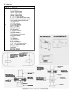
1. Read the instructions completely and carefully
before you begin. Check the kit for proper
contents (refer to the parts list and the picture
diagrams). NOTE: If the vehicle is equipped with
a manual transmission, part #3700, shift lever
extension, will be required to complete the
installation. If the vehicle is equipped with front
tow hooks, they will be removed and cannot be
reinstalled after the bumper has been lifted. If you
wish to leave the tow hooks on the vehicle, the
front bumper cannot be lifted.
2. Park the vehicle on a clean, dry, flat (level)
surface. Block the tires so the vehicle cannot roll
in either direction.
3. Disconnect both battery cables. Be sure to
disconnect the negative cable first, then the
positive cable. Remove the airbag fuses from the
fuse box in the interior and under the hood (refer
to the owner's manual).
4. Remove the four screws that mount each
doorjamb scuff plate to the body. Remove the
side kick panels by gently pulling out on the kick
panels. Be careful not to damage the plastic tabs
that mount the kick panels to the body. Manual
transmission models only: Remove the screws
that mount the shift console to the floorboard.
Pull the boot up to reveal the nut and wedge stud
that attach the upper shift lever to the lower shift
lever. Remove the nut from the right side of the
wedge stud. Install the nut on the left side of the
wedge stud. Tighten the nut to remove the stud.
After the stud has been removed, slide the upper
shift lever off of the lower shift lever. Install part
#3700 shift extension on the lower shift lever.
Insert the 1/8" x 1/2" roll pin in the hole in line with
the slot on the extension. Install the 5/16" nut on
the 5/16" x 1" bolt with the nylon toward the head
of the bolt. Align the roll pin with the slot on the
side of the tower shift lever. Slide the shift
extension onto the shift lever. Insert the 5/16" bolt
and nut assembly into the threaded hole on the
extension. The hole should be aligned with the
flat milled area at the top of the lower shift lever.
Tighten the 5/16" bolt securely. After the bolt has
been tightened, tighten the nut against the
extension.
5. Pull the carpeting back to reveal the cab
mounting bolt access covers. Remove the
access covers to expose the cab mounting bolts.
There should be one access hole on each side of
the front floorboard, and one access hole on
each side of the floorboard behind the rear seat.
On extra cab models, fold up the rear seats,
remove the side panel, and pull the carpeting
back to expose the access holes.
6. There are two ground straps that are
connected to the body and the middle cab mount
on the frame. Remove the straps from the frame.
They will be reconnected after the lifting
operation is complete.
7. There is a ground strap that runs from the back
of the engine to a stud on the firewall. Remove
the nut that mounts the ground strap to the stud
on the firewall. Install the studded ground strap
extension bracket to the stud on the firewall. The
stud on the bracket should be pointing toward the
front of the vehicle. Install the stock nut on the
stud and tighten the nut securely. Install the
ground strap to the stud protruding from the
bracket. Install a 1/4" washer and Nylock nut on
the stud. Tighten securely. We recommend the
use of Loctite® or similar adhesive on all mounting
hardware.
8. There is a wire loom that runs to the battery
and the driver's side fender well. This wire loom
is attached to the driver's side of the engine with
a bracket. There is a nut that attaches the bracket
to a stud protruding from the engine. Remove the
nut from the stud. Remove the bracket from the
stud. Remove the wire loom from the bracket.
The bracket will be repositioned on the wire loom
and reattached to the engine after the body has
been lifted.
9. Automatic transmission model only:
Automatic transmissions are equipped with cable
operated shift and should require no
modifications. Remove the cable from any clips
that are holding the cable to the body that may
cause binding while lifting.
10. 4-wheel drive models only. If the vehicle is
equipped with electronic 4-wheel drive shift
control, remove the wire loom mounting tab from
the bracket on the rear of the transfer case under