


5
E. Prior to System Test
WARNING! Do not allow terminals of radio connectors to come in contact with any metal
from vehicle due to +12 volts being present at these terminals.
1. Reconnect negative battery terminal.
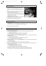
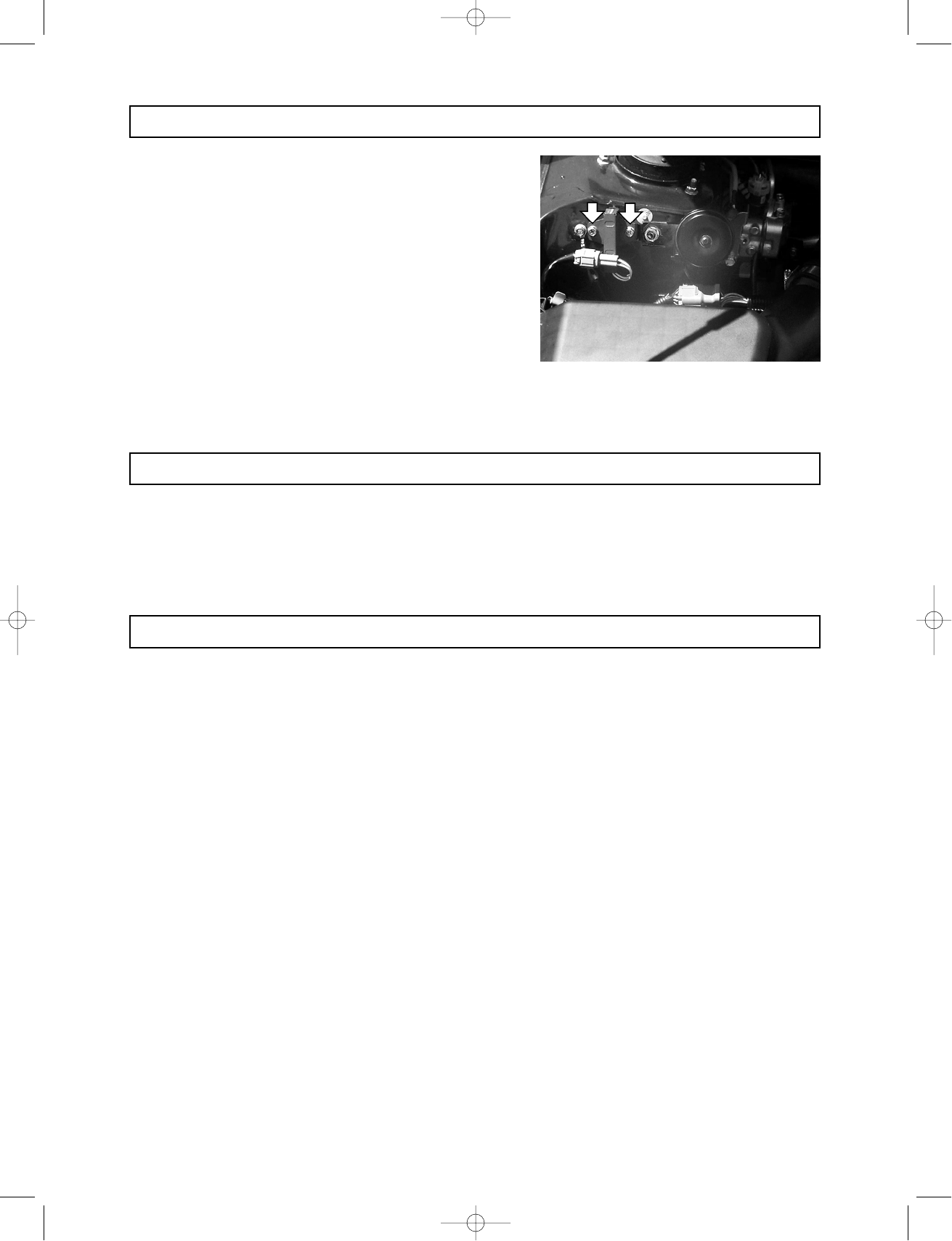
D. Horn Installation
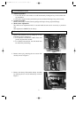
1. Locate the AT resistor in the engine compartment.
2. Remove the bolt (M8) indicated by arrow A in
Figure 1 and loose the bolt (M8) indicated by arrow
B.
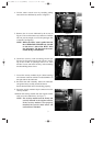
3. Mount the horn bracket by passing it behind the AT
resistor in the engine compartment.
Insert the notch of the horn bracket between the bolt
and nut indicated by arrow B, and secure both bolts
indicated by arrow A and B.
Tighten bolts to 5.4+/-1.4 ft. lbs.
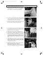
4. Locate the black 1-pin connector at the end of the
firewall wire harness, below the receiver/dryer.
5. Connect the 1-pin connector to the horn.
F. System Test
1. Exit the vehicle and close all doors.
2. Depress the LOCK/ARM button on the remote and the following should be observed:
a. All vehicle doors will lock.
b. The parking lights will flash once and the horn will chirp once.
c. Status indicator (LED) will begin to flash 1x per 2 seconds.
3. Wait 5 seconds then depress the UNLOCK/DISARM button on the remote and the following
should be observed:
a. The driver’s door will unlock.
b. The parking lights will flash twice and the horn will chirp twice.
c. The status indicator (LED) will stop flashing.
4. Wait 5 seconds then depress the UNLOCK/DISARM button on the remote and the following
should be observed:
a. All doors will unlock.
5. Depress the LOCK/ARM button on the remote to enter the armed mode.
6. Wait 5 seconds then, using the key, open a door or trunk (vehicle hood is not protected) and the
following should be observed:
a. The horn will start to sound 1x per second.
b. The parking lights will flash 1x per second.
c. The status indicator (LED) will begin to flash 2x per second.
7. With the alarm sounding, attempt to start the engine. The engine should not start.
a. If the engine starts, ensure that the starter interrupt relay is properly installed.
Figure 1
AA
AA
BB
BB
39412/SUBARU (P.01-09) 8/1/00 5:40 PM Page 5