


9-2
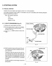
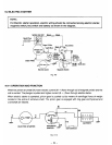
ELECTRIC STARTER
i".
I
NOTE;
1
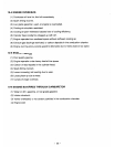
For Electric starter operation, electric wiring should be connected among electric starter,
magnetic switch, key switch and battery as shown in the diagram.
Ignition Coil Unit
Black
I.
I
Green
I
"'
u
Electric starter Magnetic Switch
Fig.
9-9
wire
9-2-1
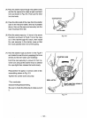
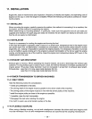
OPERATION AND FUNCTION
When key switch is turned
ON,
lower electric current
(M
-)
flows through coil
of
magnetic switch and the
coil is excited. The plunger
is
pulled and higher current
(S
-
)
flows
through electric starter.
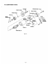
When electric starter
is
operated, pinion gear
is
pushed
out
by means of centrifugal force of weight
located in the spline of armature shaft. The pinion gear is engaged with ring gear and flywheel and
crankshaft are rotated.
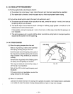
M
'*M
S
S
c
c
BAlTERY
ELECTRIC STARTER
KEY
SWITCH
I'
Fig.
9-70
-
54-