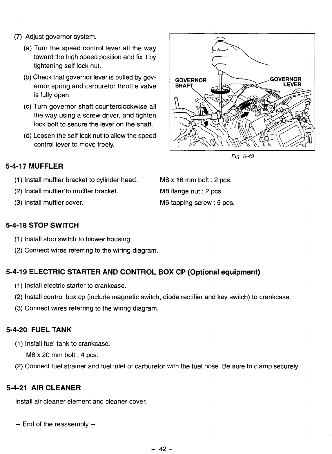
(7)
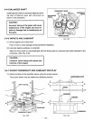
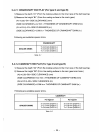
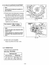
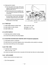
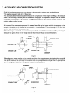
Adjust governor system.
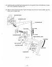
(a) Turn the speed control lever all the way
toward the high speed position and fix it by
tightening self lock nut.
(b) Check that governor lever is pulled by gov-
ernor spring and carburetor throttle valve
is fully open.
(c) Turn governor shaft counterclockwise all
the way using a screw driver, and tighten
lock bolt to secure the lever on the shaft.
(d)
Loosen the self Jock nut to allow the speed
control lever to move freely.
5-4-1
7
MUFFLER
GOVERNOR
Fig.
5-43
(1)
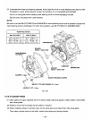
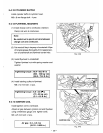
Install muffler bracket to cylinder head.
M8
x
16
mm bolt
:
2
pcs.
(2)
Install muffler-to muffler bracket.
M8
flange nut
:
2
pcs.
(3)
Install muffler cover.
M6
tapping screw
:
5
pcs.
5-4-18
STOP
SWITCH
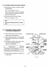
(1)
Install stop switch to blower housing.
(2)
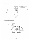
Connect wires referring to the wiring diagram.
5-4-19 ELECTRIC STARTER
AND
CONTROL
BOX
CP (Optional equipment)
(1)
Install electric starter to crankcase.
(2)
Install control
box
cp (include magnetic switch, diode rectifier and key switch) to crankcase.
(3)
Connect wires referring to the wiring diagram.
5-4-20
FUEL TANK
(1)
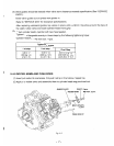
Install fuel tank to crankcase.
M8
x
20
mm bolt
:
4
pcs.
(2)
Connect fuel strainer and fuel inlet of carburetor with the fuel hose. Be sure to clamp securely.
5-4-21
AIR
CLEANER
Install air cleaner element and cleaner cover
-
End of the reassembly
-
-
42-


