


12
Note:
It may be necessary to reset the Controller.
At times it may be neccessary to reset the controller. This
could happen if a fault occurs in the controller. For ex-
ample, excessive engine speed. If a fault does occur the
power unit will return to an idle and the operator will have
no control of the unit. To reset the controller, simply turn off
the power unit and restart it.
STARTUP
Before starting the engine make sure the ow selector
switch is in the OFF position.
Note:
The power unit will not start if the ow control switch is
not in the "OFF" position.
Pull choke knob out and move the Throttle Control Switch
to the auto-idle-off or the auto-idle-on position, whichever
mode of operation the operator prefers. Ensure the ow
selector switch is in the OFF position.
Turn the Ignition Switch to the START position. After the
engine starts, release the switch.
Gradually push in the choke knob as the engine begins to
idle smoothly.
Allow the engine to warm up.
Connect hoses and the tool as desrcribed on page 8 and
10.
FOR 8 GPM OPERATION
For 8 gpm operation, select mode of operation with the
Throttle Control switch, either auto-idle-on or the auto-idle-
off position. Move the ow selector switch to the 8 gpm
position.
When nished operating the tool, move the ow selector
switch to the OFF position.
FOR 12 GPM OPERATION
For 12 gpm operation, select mode of operation with the
Throttle Control Switch, either auto-idle-on or the auto-idle-
off position. Move the ow selector switch to the 12 gpm
position.
When nished operating the tool, move the ow selector
switch to the OFF position.
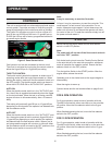
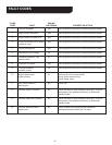
CONTROLS
This unit is equipped with an advanced proportional engine
control system. It provides a means of controlling engine
speed by adjusting the fuel control lever with an actuator.
The Power Unit provides one circuit, with an oil ow of 8
gpm/30 lpm up to 2000 psi/140 bar or 12 gpm/45 lpm up
to 2000 psi/140 bar with a factory-programmed electronic
governed engine throttle.
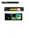
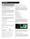
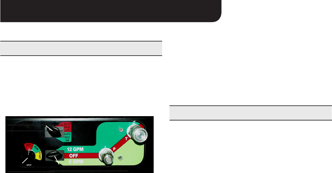
Figure 3. Panel Control Valve
One hydraulic tool can be connected to the tool circuit.
The circuit is activated by turning the ow control switch to
either the 8 gpm/30 lpm or 12 gpm/45 lpm setting.
THROTTLE CONTROL
The throttle control permits the operator to select one of 2
operating modes after the engine has warmed up. When
starting the engine, make sure the ow selector switch is in
the OFF position. The throttle control switch can be set in
either the AUTO-IDLE-ON or AUTO-IDLE-OFF positions.
AUTO-ON
When the throttle control switch is in the "AUTO-ON" posi-
tion, the oil ow is regulated automatically when the trigger
on the tool activated. When the tool is not being used the
engine will return to idle automatically, after a 10 second
delay.
This setting will produce 8 gpm/30 lpm or 12 gpm/45 lpm
depending on which postion the operator has selected with
the ow selector switch.
AUTO-OFF
When the throttle control switch is in the "AUTO-OFF" posi-
tion, the engine speed is held to maintain 8 gpm/30 lpm or
12 gpm/45 lpm depending on which position the operator
has selected with the ow selector switch. When a tool is
not being used the engine will not return to idle until either
the ow selector switch is turned to the OFF position or the
throttle control switch is turned to AUTO-ON.
ignition switch
flow selector
switch
throttle control
switch
THROTTLE CONTROL
SWITCH
FLOW SELECTOR SWITCH
IGNITION SWITCH
OPERATION