


12 ► CD12 User Manual
12.
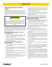
NOTICE
Manually screw the corresponding drill bit from
below onto the drill bit adapter. Manual tightening
is sufcient because the drill bit will automatically
tighten further during the drilling operation.
Connect the core drill to a water supply. The maxi-
mum allowed water pressure is 60 psi/4 bar.
13.
CAUTION
Monitor the water supply continuously to ensure that
sufcient water is supplied to the cut surface to avoid
unnecessary wear of drilling equipment.
Connect the core drill to a hydraulic power supply.
Note the correct connections for the ow of uid to
the core drill.
DRILLING A HOLE
1.
CAUTION
When drilling into a structure that might contain
electrical wiring, be sure to know the location of the
wiring and avoid drilling into it. The housing can carry
electrical current from live electrical wires into which
the drill is accidentally drilled resulting in injury or
death.
Open the water supply valve and adjust the water
ow as required. It may be necessary to adjust the
water as the drill bit advances in the hole.
2. Start the core drill by moving the drill valve lever to
ON.
3. While holding the feed handle, pull the carriage lock
knob out to release the carriage from the mast.
4. Feed to drill to the work face and begin drilling. Start
slowly to allow the drill bit to create a full seat in the
hole.
5. When the drilling is nished, return the carriage to
the top of the mast to where the carriage lock snaps
into the hole in the mast to lock the carriage in place.
6. Turn off the core drill.
7. Turn off the water
8. Turn off the hydraulic system.
9. Remove the drill bit. It may be necessary to use the
wrenches to loosen and remove the drill bit.
10. Loosen and back out the drill mount locking screw.
Remove the core drill and dovetail block from the
carriage.
11. Release the vacuum or remove the anchor screw to
move the drill stand.
ADJUSTING THE GUIDE BUSHINGS
1. Loosen the pinch screws that lock the bushing caps.
Tighten or loosen the bushing caps as necessary
to remove play between the carriage and the mast.
2. Tighten the pinch screws to lock the bushing caps.
To replace the guide bushings:
3. Remove the top carry handle and stop plate.
4. Pull the carriage lock knob to release the carriage.
Pull the carriage up and off the mast.
5. Remove the guide bushings from the carriage.
6. Loosen the pinch screws that lock the bushing caps
and back out the bushing caps.
7. Install the new guide bushings.
8. Place the carriage on the mast while making sure
the guide bushings align with the grooves in the
mast.
9. Slide the carriage onto the mast until the carriage
lock knob engages the mast.
10. Tighten the bushing caps to remove all carriage play.
Tighten the pinch screws to lock the bushing caps.
Replace the stop plate and the top carry handle
OPERATION