


10 ► CD12 User Manual
GENERAL OPERATION
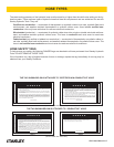
The tool comes with a set of accessories which may be
customized by each purchaser, so as to facilitate per-
formance of all work occurring within the scope of his
specic application. Tools included are for mounting and
dismounting.
• Single-head wrench SW 24
• Single-head wrench SW 32
• Single-head wrench SW 41
• Hex wrench SW 5
DRILL BIT INSTALLATION
WARNING
Before you start changing the drill bit, make sure that
the tool is disconnected from the power source in
order to avoid unintentional operation of the tool and
injury.
Use a single-head wrench SW 24 (small drill bit) or SW
41 (large drill bits) and a single-head wrench SW 32 to
manually unscrew the drill bit to be removed and to
screw on the new one. There is no need to use any ad-
ditional tools.
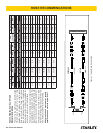
DIMENSION OF THE DRILL BIT
Drill head thread: male 1 – 1/4 in. UNC and female R
1/2 in.
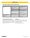
Which drill bit at which speed?
Gear #1 Gear #2 Gear #3
Speed (1/min) 610 1440 2880
Drill bit dia. (mm) 100–162 40–100 20–40
Cutting speed (m/s) 3.2–5.6 3.2–7.2 3.2–6.4
CHECK THE POWER SOURCE
1. Using a calibrated owmeter and pressure gauge,
check that the hydraulic power source develops a
ow of 7–9 gpm/26–34 lpm at 950–2000 psi/66–138
bar.
2. Make sure the hydraulic power source is equipped
with a relief valve set to open at 2100–2250 psi/145–
155 bar.
3. Check that the hydraulic circuit matches the tool for
open-center (OC) operation.
CHECK THE TOOL
1. Make certain all tool accessories are correctly in-
stalled. Failure to install tool accessories properly
can result in damage to the tool or personal injury.
2. Check the equipment for signs of oil leaks. If leaks
are observed, do not use the tool; have the equip-
ment serviced before use.
3. Check fasteners for tightness.
4. Check the tool and hydraulic system for proper op-
eration and performance.
5. If the equipment does not appear to operate prop-
erly, have it serviced before use.
CONNECT HOSES
1. Wipe all hose couplers with a clean lint-free cloth
before making connections.
2. Connect the hoses from the hydraulic power source
to the tool ttings or quick disconnects. It is good
practice to connect the return hose rst and discon-
nect it last to eliminate or reduce trapped pressure
for easier quick-connect tting attachment.
NOTE:
If uncoupled hoses are left in the sun, pressure in-
crease within the hoses can make them difcult to
connect. When ever possible, connect the free ends
of hoses together.
3. Observe the ow indicators stamped on the hose
couplers to ensure that the ow is in the proper di-
rection. The female coupler on the drill is the inlet
coupler.
4. Cycle the control valve momentarily. If the drill does
not operate, the hoses might be reversed. Verify
correct connection of the hoses before continuing.
OPERATION