


25
SECTION 4 – ADJUSTMENTS & REPAIRS
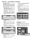
4.2 SERVICE BRAKE & PARK BRAKE
ADJUSTMENT (Continued)
8. Operate machine on smooth flat surface at
approximately 1/2 speed.
9. Apply brake firmly. Machine should stop in a
straight line and not pull to either the right or the
left. Also both rear tires should begin to skid
evenly.
10. If the machine pulls to the left or the left tire skids
before the right, tighten the right brake adjustment
nut 1/4 turn clockwise.
11. If the machine pulls to the right or the right tire
skids before the left, tighten the left brake
adjustment nut 1/4 turn clockwise.
12. Continue until the machine stops straight and both
tires skid evenly.
WARNING
DO NOT attempt any adjustments, maintenance,
service or repairs with the engine running. STOP
engine. Set park brake. Shift transmission to Neutral.
Remove key. Remove spark plug wire from spark
plug and secure away from plug. Engine and
components are HOT. Avoid serious burns, allow all
parts to cool before working on machine.
4.3 BATTERY
NOTE: The battery in this machine is maintenance-free.
It has been filled to the proper level with acid and is
sealed. Do not attempt to open the battery.
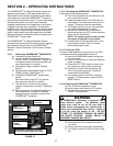
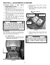
4.3.1. Battery Removal
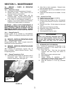
1. The battery is located under operator’s seat.
Remove seat knobs and carefully tilt forward to
expose battery. See Figure 4.3.
FIGURE 4.3
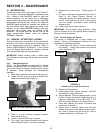
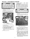
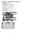
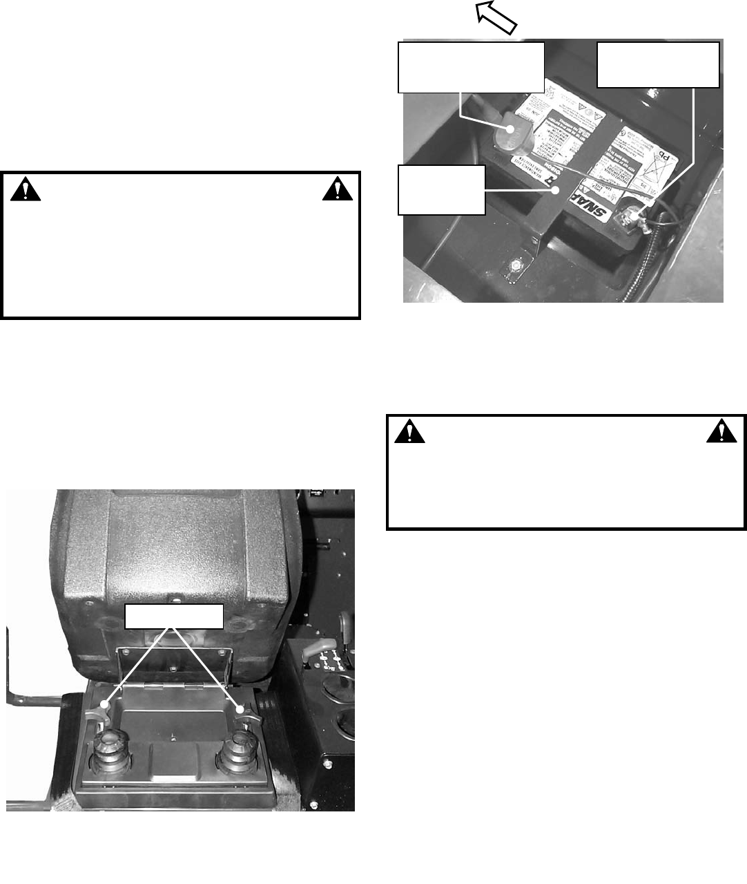
2. Observe and note cable positions on battery.
See Figure 4.4.
3. Disconnect cables from battery terminals,
disconnecting BLACK (Negative) cables first.
Retain hardware.
FIGURE 4.4
4. Remove battery retaining strap hardware and
carefully lift battery out of battery tray. See
Figure 4.4.
WARNING
Cables must be connected to battery terminals in the
proper position as shown in Figure 4.4. DO NOT
attempt to charge battery while installed on the
Machine. DO NOT use “BOOST” chargers on the
battery.
SEAT KNOBS
FRONT OF MACHINE
27
POSITIVE (+) CABLES
(RED) WITH TERMINAL
COVER
NEGATIVE (-)
CABLES (BLACK)
BATTERY
RETAINING
STRAP