


16
SECTION 2 – OPERATING INSTRUCTIONS
2.2 CONTROLS – FUNCTION AND OPERATION
(Continued from previous page)
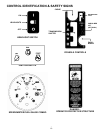
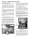
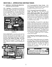
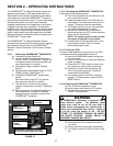
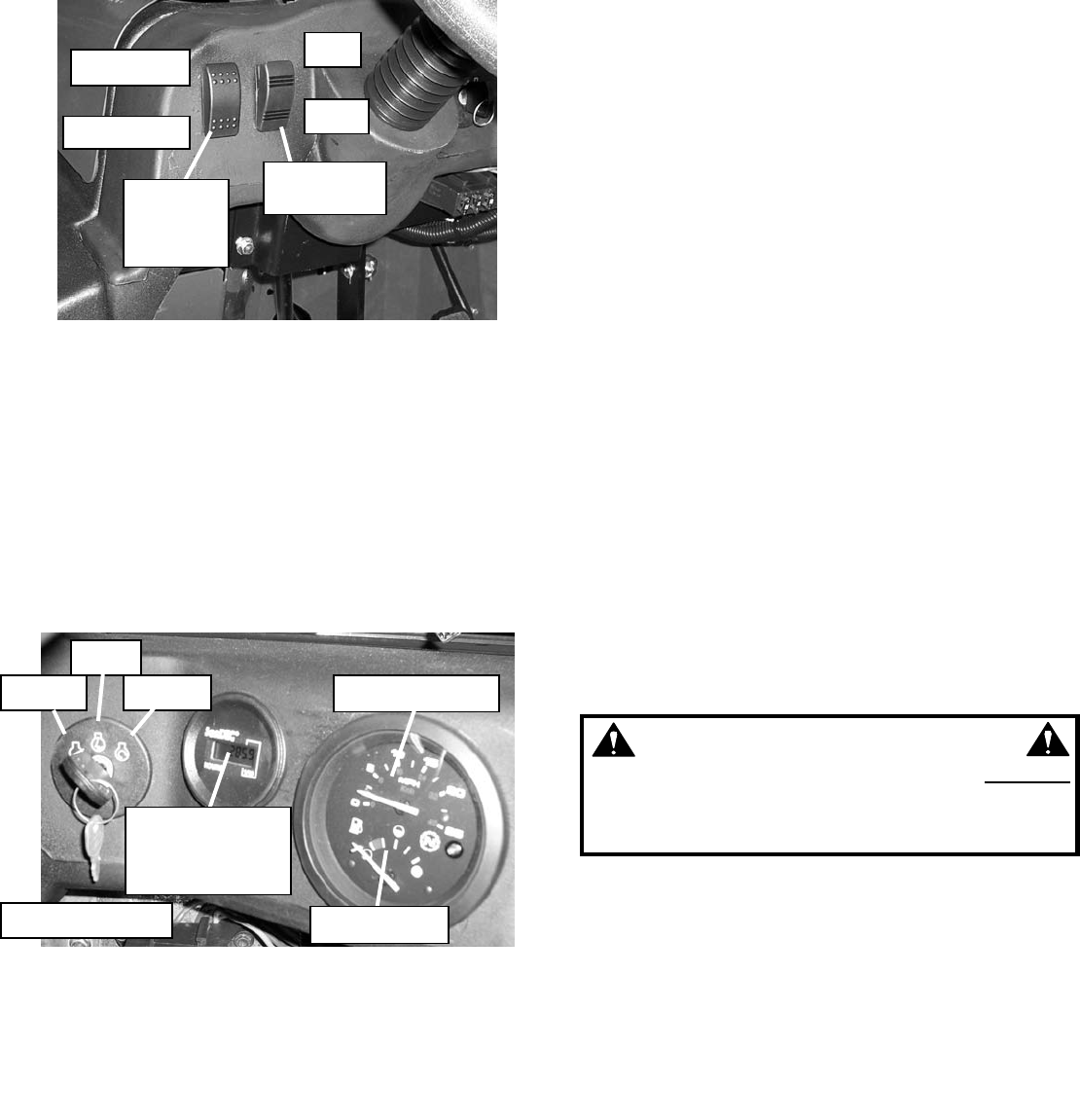
2.2.9. Headlights. The headlights are controlled by a
rocker switch, located on the dash to the immediate left
of the steering wheel. See Figure 2.5. Push the switch
up to turn the headlights on. Push the switch down to
turn the headlights off. Note: The engine ignition switch
must be in the “RUN” position for the headlights to
operate. Repair non-functional headlights before
operating machine and keep lenses clean.
FIGURE 2.5
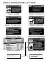
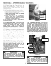
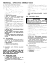
2.2.10. Ignition Switch. The ignition switch has three
positions – Stop, Run, and Start. See Figure 2.6. Turn
key and hold momentarily at “Start” position to crank
the engine. After starting, release key to “Run” position.
Turn key to “Stop” position to stop engine. Turning the
key to the “Run” position will enable use of the
headlights and the 12 volt accessory plug. However,
when using the headlights or accessory plug, the
engine should be running to prevent discharging the
battery.
FIGURE 2.6
2.2.11. Speedometer/Fuel Gauge Combo. Both
functions are contained within the one dial. See Figure
2.6. Speedometer measures ground speed of unit.
Fuel gauge indicates amount of fuel in tank.
2.2.12. Hourmeter/Tachometer/ServiceMinder
Combo. See Figure 2.6. With ignition off, LCD
readout displays hours engine used. With engine
started, readout displays RPM’s. After first seven (7)
hours of use, and every forty-nine (49) hours thereafter,
the ServiceMinder displays a message indicating oil
change is required. The message will be displayed for
two (2) hours, and will continue even if oil is changed
within the two hour period. After two hours, whether oil
is changed or not, display will revert back to
hourmeter/tachometer function.
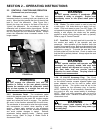
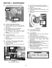
2.2.13. Cargo Bed. The manual lift * cargo bed is
secured in the lowered position by two spring latches
located on either side of the machine. Pull outward on
the latch lever (located behind the left cargo bed lift
handle) to release the bed, and lift via the handle. Use
the prop rod to secure the bed in the fully raised
position. (NOTE: make sure slot in bottom of prop rod
fully drops onto catch bolt in machine frame; failure to
do so can result in serious injury.) The tailgate can be
opened by flipping open the two tailgate latches located
on either side of the tailgate and dropping gate down.
* An electrically operated bed lift kit is available.
Contact dealer for details.
2.2.14. Powerlink™ Generator System (not on all
models). See Pages 18-19 for details on the Powerlink
generator.
2.2.15. Warn™ Electric Winch (not on all models).
The winch switch is located on the dashboard next to
the headlight switch, to the left of the steering wheel.
Pushing the switch down lets cable out; pushing the
switch up pulls cable in. See Figure 2.5. Refer to
manuals supplied with literature package for
comprehensive instructions on safe use and
maintenance of electric winch.
WARNING
The winch switch on the utility vehicle does not
automatically cut out when cable is fully retracted.
To avoid damage to winch and/or vehicle, inspect
cable regularly while retracting.
STOP
RUN
START
IGNITION SWITCH
HOURMETER /
TACHOMETER /
SERVICEMINDER
DISPLAY
SPEEDOMETER
FUEL GAUGE
OFF
ON
CABLE OUT
CABLE IN
WINCH
SWITCH
(NOT ALL
MODELS)
HEADLIGHT
SWITCH
16